 Toyota Land Cruiser Service ManualSuspension & Axle
Rear upper and lower control ARM
Rear upper and lower control ARM
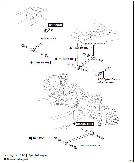
COMPONENTS
INSTALLATION
Installation is in the reverse order of removal (SA-182 ).
REMOVAL
1. REMOVE REAR WHEEL
Torque: 131 N·m (1,340 kgf·cm, 97 ft·lbf)
2. SUPPORT REAR AXLE HOUSING WITH JACK
3. REMOVE UPPER CONTROL ARM
(a) Disconnect the ABS speed sensor wire harness.
(b) RH side: Remove the bolt and heat insulator.
Torque: 18 N·m (185 kgf·cm, 13 ft·lbf)
(c) Remove the 2 nuts, washers, bolts and upper control arm.
Torque: 150 N·m (1,530 kgf·cm, 111 ft·lbf)
HINT: At the time of installation, after stabilizing the suspension, torque the nuts.
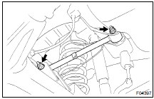
4. REMOVE LOWER CONTROL ARM

Remove the 2 nuts, washers, bolts and lower control arm.
Torque: 150 N·m (1,530 kgf·cm, 111 ft·lbf)
HINT: At the time of installation, after stabilizing the suspension, torque the nuts.
Coil spring and rear shock absorber
Differential locking system
Front axle hub
Front differential carrier
Front drive shaft
Front differential side gear shaft oil seal
Front lower suspension ARM
Front shock absorber
Front stabilizer bar
Front torsion bar spring
Front upper suspension ARM
Front wheel alignment
Front wheel hub bolt
Rear axle shaft
Rear differential carrier
Rear differential carrier (w/ Diff. Lock)
Rear differential carrier (w/ LSD)
Rear differential front oil seal
Rear lateral control rod
Rear stabilizer bar
Rear upper and lower control ARM
Rear wheel hub bolt
Steering knuckle
Tire and wheel
Troubleshooting
Toyota Land Cruiser Service Manual
Categories
