 Toyota Land Cruiser Service ManualSuspension & Axle
Front stabilizer bar
Toyota Land Cruiser
Service Manual
Front stabilizer bar
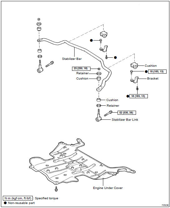
COMPONENTS
INSTALLATION
Installation is in the reverse order of removal (SA-81 ).
REMOVAL
1. REMOVE ENGINE UNDER COVER
2. REMOVE LH AND RH STABILIZER BAR LINKS
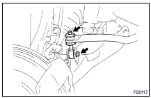
(a) Remove the nut, bolt, 2 retainers, 2 cushions and stabilizer bar link.
Torque: Bolt: 52 N·m (530 kgf·cm, 38 ft·lbf) Nut: 25 N·m (250 kgf·cm, 18 ft·lbf)
(b) Employ the same manner described above to the other side.
3. REMOVE STABILIZER BAR
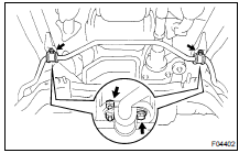
(a) Remove the 4 bolts, 2 brackets and 2 cushions.
Torque: 18 N·m (185 kgf·cm, 13 ft·lbf)
(b) Remove the stabilizer bar.
More about «Suspension & Axle»:
Coil spring and rear shock absorber
Differential locking system
Front axle hub
Front differential carrier
Front drive shaft
Front differential side gear shaft oil seal
Front lower suspension ARM
Front shock absorber
Front stabilizer bar
Front torsion bar spring
Front upper suspension ARM
Front wheel alignment
Front wheel hub bolt
Rear axle shaft
Rear differential carrier
Rear differential carrier (w/ Diff. Lock)
Rear differential carrier (w/ LSD)
Rear differential front oil seal
Rear lateral control rod
Rear stabilizer bar
Rear upper and lower control ARM
Rear wheel hub bolt
Steering knuckle
Tire and wheel
Troubleshooting
Toyota Land Cruiser Service Manual / Suspension & Axle / Front stabilizer bar
Toyota Land Cruiser Service Manual
Categories

© 2011-2026 Copyright www.tlacruiser.com