 Toyota Land Cruiser Service ManualEngine Mechanical
Disassembly
Disassembly
1. INSTALL ENGINE TO ENGINE STAND
2. REMOVE TIMING BELT AND PULLEYS ( EM-15 )
3. REMOVE CYLINDER HEAD ( EM-35 )
4. REMOVE WATER BYPASS PIPE
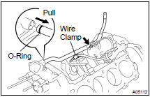
(a) Disconnect the wire clamp (for knock sensor 1, 2) from the bracket of the water bypass pipe.
(b) Remove the bolt.
(c) Pull out the water bypass pipe from the water pump.
(d) Remove the O-ring from the water bypass pipe.
5. REMOVE STARTER ( ST-5 )
6. REMOVE KNOCK SENSORS ( SF-55 )
7. DISCONNECT ENGINE WIRE FROM LH SIDE OF CYLINDER BLOCK
(a) Remove the 2 bolts and the engine wire cover from the LH side of the cylinder block.
(b) Remove the bolt, disconnect the bracket on the engine wire from the cylinder block.
8. DISCONNECT ENGINE WIRE FROM RH SIDE OF CYLINDER BLOCK
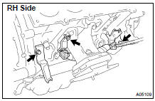
Remove the 2 bolts, and disconnect the 2 brackets on the engine wire from the cylinder block.
9. REMOVE OIL COOLER PIPE BRACKET FOR A/T
Remove the bolt and bracket.
10. REMOVE ENGINE MOUNTING BRACKETS
Remove the 4 bolts and the mounting bracket. Remove the 2 mounting brackets
11. REMOVE WATER PUMP ( CO-6 )
12. REMOVE NO.2 OIL PAN ( LU-8 )
13. REMOVE OIL PAN BAFFLE PLATE
14. REMOVE NO.1 OIL PAN ( LU-8 )
15. REMOVE OIL STRAINER
16. REMOVE OIL PUMP ( LU-8 )
17. REMOVE ENGINE COOLANT DRAIN UNIONS
Remove the 2 drain unions.
18. REMOVE REAR OIL SEAL RETAINER
(a) Remove the 7 bolts.
(b) Using a screwdriver, ply off the oil seal retainer and the main bearing cap with a screwdriver.
(c) Remove the O-ring.
19. CHECK CONNECTING ROD THRUST CLEARANCE
Using a dial indicator, measure the thrust clearance while moving the connecting rod back an a forth.
Standard thrust clearance: 0.160 - 0.290 mm (0.0063 - 0.0138 in.) Maximum thrust clearance: 0.35 mm (0.0138 in.)
If the thrust clearance is greater than the maximum, replace the connecting rod assembly(s). If necessary, replace the crankshaft.
Connecting rod thickness: 22.880 - 22.920 mm (0.9008 - 0.9024 in.)
20. REMOVE CONNECTING ROD CAPS AND CHECK OIL CLEARANCE
(a) Check the matchmarks on the connecting rod and cap to ensure correct reassembly.
(b) Remove the 2 connecting rod cap bolts.
(c) Using the 2 removed connecting rod cap bolts, remove the connecting rod cap and the lower bearing by wiggling the connecting rod cap right and left.
HINT: Keep the lower bearing inserted with the connecting rod cap.
(d) Clean the crank pin and the bearing.
(e) Check the crank pin and the bearing for pitting and scratches.
If the crank pin or the bearing is damaged, replace the bearings.
If necessary, replace the crankshaft.
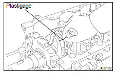
(f) Lay a strip of plastigage across the crank pin.
(g) Install the connecting rod cap with the 2 bolts.
( EM-107 )
NOTICE: Do not turn the crankshaft.
(h) Remove the 2 bolts, the connecting rod cap and the lower bearing. (See procedure (b) and (c) above)
(i) Measure the plastigage at its widest point.
Standard oil clearance: 0.027 - 0.053 mm (0.0011 - 0.0021 in.) Maximum oil clearance: 0.065 mm (0.0026 in.)
If the oil clearance is greater than the maximum, replace the bearings. If necessary, replace the crankshaft.
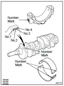
HINT: If using a standard bearing, replace it with the one having the same number. If the number of the bearing cannot be determined, sum up the numbers imprinted on the connecting rod cap and the crankshaft, then select the one with the same number as the total. There are 6 sizes of standard bearings, marked "2", "3", "4", "5", "6" and "7".
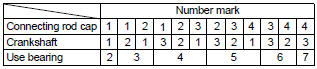
EXAMPLE: Connecting rod cap "3" + Crankshaft "1" = Total number 4 (Use bearing "4")
Reference
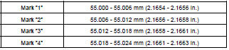
Connecting rod big end inside diameter:
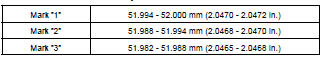
Crankshaft crank pin diameter:
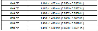
Standard sized bearing center wall thickness:
(j) Completely remove the plastigage.
21. REMOVE PISTON AND CONNECTING ROD ASSEMBLIES
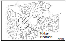
(a) Using a ridge reamer, remove all the carbon from the top of the cylinder.
(b) Push the piston, connecting rod assembly and upper bearing through the top of the cylinder block.
HINT:
- Keep the bearings, the connecting rod and the cap together.
- Arrange the piston and connecting rod assemblies in correct order.
22. CHECK CRANKSHAFT THRUST CLEARANCE
Using a dial indicator, measure the thrust clearance while prying the crankshaft back and forth with a screwdriver.
Standard thrust clearance: 0.020 - 0.220 mm (0.0008 - 0.0087 in.) Maximum thrust clearance: 0.30 mm (0.0118 in.)
If the thrust clearance is greater than the maximum, replace the thrust washers as a set.
Thrust washer thickness: 2.440 - 2.490 mm (0.0961 - 0.0980 in.)
23. REMOVE MAIN BEARING CAPS AND CHECK OIL CLEARANCE
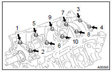
(a) Evenly loosen and remove the 10 main bearing cap bolts a little at time for several times, in the sequence shown.
(b) Using 2 screwdrivers, pry out the main bearing cap, and remove the 5 main bearing caps, the 5 lower bearings and the 2 lower thrust washers (No.3 main bearing cap only).
NOTICE: Be careful not to damage the cylinder block.
HINT: Keep the lower bearing and the main bearing cap together.
Arrange the main bearing caps and lower thrust washers in correct order.
(c) Lift out the crankshaft.
HINT: Keep the upper bearings and the upper thrust washers together with the cylinder block.
(d) Clean each main journal and bearing.
(e) Check each main journal and bearing for pitting and scratches.
If the journal or bearing is damaged, replace the bearings. If necessary, replace the crankshaft.
(f) Place the crankshaft on the cylinder block.
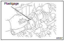
(g) Lay a strip of plastigage across each journal.
(h) Install the main bearing caps.
( EM-107 )
NOTICE: Do not turn the crankshaft.
(i) Remove the main bearing caps.
(See procedure (a) and (b) above)
(j) Measure the plastigage at its widest point.
Standard clearance: 0.040 - 0.058 mm (0.0016 - 0.0023 in.) Maximum clearance: 0.070 mm (0.0028 in.)
If the oil clearance is greater than the maximum, replace the bearings. If necessary, replace the crankshaft.
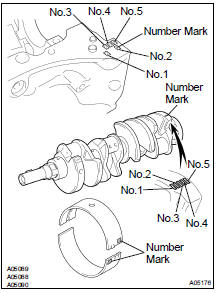
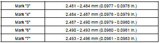
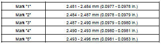
HINT: If using a standard bearing, replace it with the one having the same number. If the number of the bearing cannot be determined, sum up the numbers imprinted on the cylinder block and the crankshaft, then refer to the table below for the appropriate bearing number. There are 5 sizes of the standard bearings. For No.1 and No.5 position bearings, use bearings marked "3", "4", "5", "6" and "7". For others position bearings, use bearings marked "1", "2", "3", "4" and "5".
No.1, No.5:
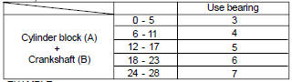
EXAMPLE: Cylinder block "08" + Crankshaft "06" = Total number 14 (Use bearing "5")
Others:
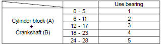
EXAMPLE: Cylinder block "08" + Crankshaft "06" = Total number 14 (Use bearing "3")
Reference
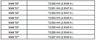
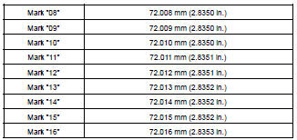
Cylinder block main journal bore diameter (A):
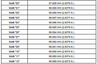
Crankshaft main journal diameter (B):
Standard bearing center wall thickness:
No.1 and No.5
Others:
(k) Completely remove the plastigage.
24. REMOVE CRANKSHAFT
(a) Lift up the crankshaft.
(b) Remove the 5 upper main bearings and the 2 upper thrust washers from the cylinder block.
HINT: Arrange the main bearing caps, bearings and thrust washers in correct order for installation.
25. CHECK FIT BETWEEN PISTON AND PISTON PIN
Try to move the piston back and forth on the piston pin.
If any movement is felt, replace the piston and pin as a set.
26. REMOVE PISTON RINGS
(a) Using a piston ring expander, remove the 2 compression rings.
(b) Remove the 2 side rails and the oil ring by hand.
HINT: Arrange the piston rings in correct order for installation
27. DISCONNECT CONNECTING ROD FROM PISTON
(a) Using a small screwdriver, pry out the 2 snap rings.
(b) Gradually heat the piston to approx. 60C (140F).
(c) Using a plastic-faced hammer and a brass bar, lightly tap out the piston pin and the pin and remove the connecting rod.
HINT:
- The piston and the pin are the set.
- Arrange the pistons, the pins, the rings, the connecting rods and the bearings in correct order for installation.
CO/HC
Compression
Cylinder block
Disassembly
Cylinder head
Inspection
Installation
Replacement
Engine unit
Idle speed
Ignition timing
Timing belt
Valve clearance
Toyota Land Cruiser Service Manual
Categories
