 Toyota Land Cruiser Service ManualEngine Mechanical
Installation
Installation
1. INSTALL RH EXHAUST MANIFOLD TO CYLINDER HEAD
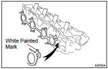
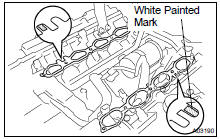
(a) Place a new gasket on the cylinder head with the white painted marks facing the manifold side.
NOTICE: Be careful of the installation direction.
(b) Install the exhaust manifold with 8 new nuts. Evenly tighten the nuts a little at a time for several times.
Torque: 44 N·m (450 kgf·cm, 32 ft·lbf)
(c) Install the heat insulator with the 4 bolts.
Torque: 7.5 N·m (77 kgf·cm, 66 in.·lbf)
2. INSTALL LH EXHAUST MANIFOLD TO CYLINDER HEAD
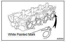
(a) Place a new gasket on the cylinder head with the white painted marks facing the manifold side.
NOTICE: Be careful of the installation direction.
(b) Install the exhaust manifold with 8 new nuts. Evenly tighten the nuts a little at a time for several times.
Torque: 44 N·m (450 kgf·cm, 32 ft·lbf)
(c) Install the heat insulator with the 4 bolts.
Torque: 7.5 N·m (77 kgf·cm, 66 in.·lbf)
3. PLACE CYLINDER HEAD ON CYLINDER BLOCK
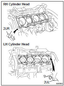
(a) Place 2 new cylinder head gaskets in position on the cylinder block.
HINT: On the rear side of the cylinder head gasket, there is a mark to distinguish the LH and RH banks, a "2UR" for the RH bank and a "2UL" for the LH bank.
NOTICE: Be careful of the installation direction.
(b) Place the 2 cylinder heads in position on the cylinder head gaskets.
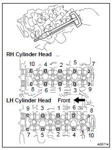
4. INSTALL CYLINDER HEAD BOLTS
HINT:
- The cylinder head bolts are tightened in 2 progressive steps (steps (c) and (e)).
- If any cylinder head bolt is broken or deformed, replace it.
(a) Apply a light coat of engine oil on the threads and under the heads of the cylinder head bolts.
(b) Install the plate washer to the cylinder head bolt.
(c) Install and evenly tighten the 10 cylinder head bolts on one side of the cylinder head a little at a time for several times as in the order shown, then do the other side as shown.
Torque: 32 N·m (325 kgf·cm, 24 ft·lbf)
If any one of the cylinder head bolts does not meet the torque specification, replace the cylinder head bolt.
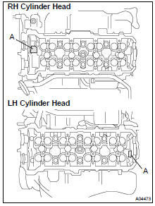
NOTICE: Do not drop the plate washer of the cylinder head bolt into A area in the illustration. It will fall down to the oil pan through the cylinder head and the cylinder block.
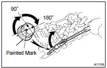
(d) Mark the front of the cylinder head bolt head with paint.
(e) Retighten the cylinder head bolts by 90 only for the first time.
(f) Then retighten them by 90 further for the second time.
(g) Check that the painted mark is now at a 180 angle to the front.
5. INSTALL SPARK PLUGS
6. ASSEMBLE EXHAUST CAMSHAFT
(a) Install the camshaft gear spring, the camshaft sub-gear and the wave washer.
HINT: Attach the pins on the gears to the gear spring ends.
(b)
(b) Using snap ring pliers, install the snap ring.
8. INSTALL CAMSHAFTS
NOTICE: Since the thrust clearance of the camshaft is small, the camshaft must be kept level while it is being removed.
Otherwise, excessive pressure is put on the cylinder head journal thrust, causing a burr on the journal and damage on the camshaft. To avoid this, follow the steps below.
(a) Set the crankshaft pulley position.
Turn the crankshaft pulley clockwise or counterclockwise, and put the timing mark of the crankshaft pulley in line with the centers of the crankshaft pulley bolt and the idler pulley bolt.
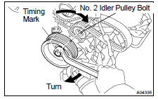
NOTICE: Having the crankshaft pulley at the wrong angle can cause the piston head and the valve head to come into contact with each other when removing the camshaft, causing damage on them. So always set the crankshaft pulley at the correct angle.
(b) Install the RH camshafts.
- Apply MP grease to the thrust portion of the intake and exhaust camshafts.
- Place the intake and exhaust camshafts.
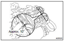
- Set the timing mark (1 dot mark) of the camshaft main gear at approx. 10 angle.
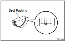
- Remove any old packing (FIPG) material from the front bearing cap.
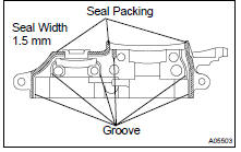
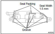
- Apply seal packing to the front bearing cap as shown in the illustration.
Seal packing: Part No. 08826-00080 or equivalent
- Install a nozzle that is cut to a 1.5 mm (0.06 in.) opening.
- Parts must be assembled within 5 minutes the seal packing application. Otherwise the material must be removed and the packing have to be reapplied.
- Immediately remove nozzle from the tube and reinstall cap.
NOTICE: Do not apply seal packing to the front bearing cap grooves
- Install the front bearing cap.
HINT: Installing the front bearing cap will determine the thrust portion of the camshaft.
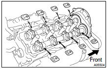
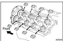
- Install the other bearing cap in the sequence shown with the arrow mark facing forward.
HINT: Align the arrow marks at the front and rear of the cylinder head with the mark on the bearing cap.
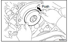
- Push in the camshaft oil seal.
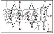
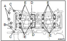
- Apply a light coat of engine oil on the threads and under the heads (D and E) of the bearing cap bolts.
HINT: Do not apply engine oil under the heads of the bearing cap bolt (A), (B) and (C).
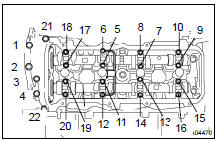
- Install the oil feed pipe and the 22 bearing cap bolts as shown.
HINT:
Bolt length:
94 mm (3.70 in.) for A
72 mm (2.83 in.) for B
25 mm (0.98 in.) for C
52 mm (2.05 in.) for D
38 mm (1.50 in.) for E
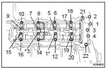
- Evenly tighten the 22 bearing cap bolts a little at a time for several times as in the sequence shown.
Torque:
Bolt C: 7.5 N·m (80 kgf·cm, 69 in.·lbf)
Others 16 N·m (160 kgf·cm, 12 ft·lbf)
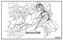
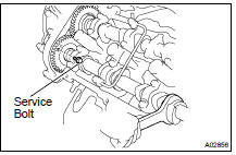
- Move a service bolt of the sub-gear upward by turning the hexagon shaped port of the exhaust camshaft with a wrench.
- Remove the service bolt.
(c) Install the LH camshafts.
- Apply MP grease to the thrust portion of the intake and exhaust camshafts.
- Place the intake and exhaust camshafts.
- Engage the intake to the exhaust gear by putting the timing marks (2 dot marks) on each gear.
- Remove any old packing (FIPG) material.
- Apply seal packing to the front bearing cap.
Seal packing: Part No. 08826-00080 or equivalent
- Install a nozzle that is cut to a 1.5 mm (0.06 in.) opening.
- Parts must be assembled within 5 minutes the seal packing application. Otherwise the material must be removed and the packing have to be reapplied.
- Immediately remove nozzle from the tube and reinstall cap.
NOTICE: Do not apply seal packing to the front bearing cap grooves.
- Install the front bearing cap.
HINT: Installing the front bearing cap will determine the thrust portion of the camshaft.
- Install the other bearing cap in the sequence shown with the arrow mark facing forward.
HINT: Align the arrow marks at the front and rear of the cylinder head with the mark on the bearing cap.
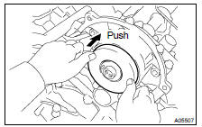
- Push in the camshaft oil seal.
- Apply a light coat of engine oil on the threads and under the heads (D and E) of the bearing cap bolts.
HINT: Do not apply engine oil under the heads of the bearing cap bolt (A), (B) and (C).
- Install the oil feed pipe and the 22 bearing cap bolts as shown.
HINT:
Bolt length:
94 mm (3.70 in.) for A
72 mm (2.83 in.) for B
25 mm (0.98 in.) for C
52 mm (2.05 in.) for D
38 mm (1.50 in.) for E
- Uniformly tighten the 22 bearing cap bolts in several passes, in the sequence shown.
Torque:
Bolt C: 7.5 N·m (80 kgf·cm, 69 in.·lbf)
Others 16 N·m (160 kgf·cm, 12 ft·lbf)
- Move a service bolt of the sub-gear upward by turning the hexagon shaped port of the exhaust camshaft with a wrench.
- Remove the service bolt.
9. CHECK AND ADJUST VALVE CLEARANCE ( EM-4 )
Turn the camshaft and the position the cam lobe upward, and check and adjust the valve clearance.
10. INSTALL SEMI-CIRCULAR PLUGS
(a) Remove any old packing (FIPG) material.
(b) Apply seal packing to the semi-circular plug grooves.
Seal packing: Part No. 08826-00080 or equivalent
(c) Install the 4 semi-circular plugs to the cylinder heads.
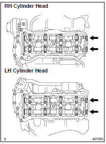
11. INSTALL CYLINDER HEAD COVER
(a) Remove any old packing (FIPG) material.
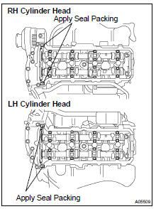
(b) Apply seal packing to the cylinder heads as shown in the illustration.
Seal packing: Part No. 08826-00080 or equivalent
(c) Install the gasket to the cylinder head cover.
(d) Install the seal washer to the bolt.
(e) Install the cylinder head cover with the 18 bolts. Evenly tighten the bolts a little at a time for several times. Install the 2 cylinder head covers.
Torque: 6.0 N·m (60 kgf·cm, 53 in.·lbf)
12. INSTALL ENGINE HANGERS
Torque: 37 N·m (380 kgf·cm, 27 ft·lbf)
13. INSTALL OIL DIPSTICK AND GUIDE FOR ENGINE
LAND CRUISER (RM1071U)
14. INSTALL REAR WATER BYPASS JOINT
(a) Install 2 new gaskets to the cylinder head.
(b) Install the 4 nuts holding the water bypass joint to the cylinder heads. Alternately tighten the nuts.
Torque: 18 N·m (185 kgf·cm, 13 ft·lbf)
15. INSTALL FRONT WATER BYPASS JOINT
Install 2 new gaskets and the water bypass joint with the 4 nuts.
Alternately tighten the nuts.
Torque: 18 N·m (185 kgf·cm, 13 ft·lbf)
16. INSTALL WATER INLET AND INLET HOUSING ASSEMBLY
17. ASSEMBLE UPPER AND LOWER INTAKE MANIFOLDS
(a) Install the 2 delivery pipes and the 8 injectors ( SF-27 ).
(b) Install new 2 gaskets, the fuel pressure regulator and the fuel pulsation damper.
(c) Install the fuel return hose to the lower intake manifold with the 3 bolts.
(d) Connect the fuel return hose to the fuel pressure regulator.
18. INSTALL INTAKE MANIFOLD ASSEMBLY
(a) Place 2 new gaskets on the cylinder heads with white painted mark facing upward.
NOTICE:
- Align the port holes of the gasket and cylinder head.
- Be careful of the installation direction
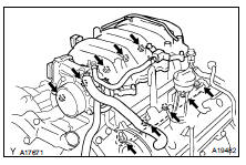
(b) Place the intake manifold assembly on the cylinder heads.
(c) Install and uniformly tighten the 6 bolts and the 4 nuts in several passes.
Torque: 18 N·m (185 kgf·cm, 13 ft·lbf)
(d) Install the EVAP pipe to the intake manifold with the 2 bolts.
(e) Connect the wire protector to the intake manifold with the 2 bolts.
(f) Install the engine wire to the engine hanger.
(g) Install the engine wire to the LH No.1 timing belt rear plate.
(h) Install the engine wire to the bracket.
(i) Connect the wire protector to the rear water bypass joint and RH cylinder head with the 2 bolts.
(j) Install the 2 ground cables to the RH and LH cylinder head.
(k) Install the guide for A/T bracket to the LH cylinder head.
(l) Connect the 2 wire clamps to the wire clamp bracket on the RH delivery pipe.
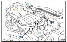
(m) Connect the fuel pressure regulator vacuum hose to the fuel pressure regulator pipe.
(n) Connect the PCV hose to the PCV valve on the LH cylinder head.
(o) Connect the EVAP hose (from charcoal canister) to the VSV for EVAP.
(p) Connect the EVAP hose (from charcoal canister) to the EVAP pipe on the intake manifold.
(q) Connect the EVAP hose (from intake air connector) to EVAP pipe on the intake manifold (r) Connect the PS air hose to intake manifold.
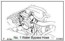
(s) Connect the No.1 water bypass hose (from water inlet housing) to throttle body.
(t) Connect the throttle control connector.
(u) Connect the VSV connector for EVAP.
(v) Connect the 8 injector connectors.
(w) Connect the ECT sensor.
(x) Connect the water sender gauge.
(y) Connect the 8 ignition coil connectors.
(z) Connect the 2 oxygen sensor connectors.
19. CONNECT FUEL INLET HOSE ( SF-24 )
20. INSTALL TIMING BELT REAR PLATES
(a) Install the RH timing belt rear plates.
Install the No.1 timing belt rear plate to the cylinder head with the 3 bolts and the stud bolt.
Torque: 7.5 N·m (80 kgf·cm, 66 in.·lbf)
(b) Install the LH timing belt rear plates.
- Connect the wire clamp to the No.1 timing belt rear plate.
- Install the No.1 timing belt rear plate to the cylinder head with the 3 bolts.
Torque: 7.5 N·m (80 kgf·cm, 66 in.·lbf)
21. INSTALL V-BANK COVER
Install the 3 V-bank covers.
Torque: 7.5 N·m (80 kgf·cm, 66 in.·lbf)
22. INSTALL IGNITION COILS ( IG-6 )
23. INSTALL OIL DIPSTICK AND GUIDE FOR A/T
24. INSTALL FRONT EXHAUST PIPE ( EM-1 15)
25. INSTALL PS PUMP ( EM-81 )
26. INSTALL CAMSHAFT POSITION SENSOR ( IG-10 )
27. INSTALL CAMSHAFT TIMING PULLEYS ( EM-22 )
28. CONNECT TIMING BELT TO CAMSHAFT TIMING PULLEYS ( EM-22 )
29. CHECK ENGINE OIL LEVEL
CO/HC
Compression
Cylinder block
Disassembly
Cylinder head
Inspection
Installation
Replacement
Engine unit
Idle speed
Ignition timing
Timing belt
Valve clearance
Toyota Land Cruiser Service Manual
Categories
