 Toyota Land Cruiser Service ManualIntroduction
For all of vehicles
For all of vehicles
PRECAUTION
1. FOR VEHICLES EQUIPPED WITH SRS AIRBAG AND SEAT BELT PRETENSIONER
(a) The LAND CRUISER is equipped with an SRS (Supplemental Restraint System), such as the driver airbag, front passenger airbag assembly and seat belt pretensioner.
Failure to carry out service operations in the correct sequence could cause the supplemental restraint system to unexpectedly deploy during servicing, possibly leading to a serious accident.
Further, if a mistake is made in servicing the supplemental restraint system, it is possible the SRS may fail to operate when required. Before servicing (including removal or installation of parts, inspection or replacement), be sure to read the following items carefully, then follow the correct procedure described in this manual.
(b) GENERAL NOTICE
- Malfunction symptoms of the supplemental restraint system are difficult to confirm, so the diagnostic trouble codes become the most important source of information when troubleshooting. When troubleshooting the supplemental restraint system, always inspect the diagnostic trouble codes before disconnecting the battery ( DI-692 ).
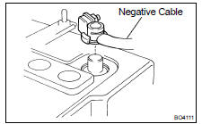
- Work must be started after 90 seconds from the
time the ignition switch is turned to the "LOCK" position
and the negative (-) terminal cable is disconnected
from the battery.
(The supplemental restraint system is equipped with a back-up power source so that if work is started within 90 seconds of disconnecting the negative (-) terminal cable from the battery, the SRS may deploy.) When the negative (-) terminal cable is disconnected from the battery, memory of the clock and audio systems will be cancelled. So before starting work, make a record of the contents memorized by the each memory system. Then when work is finished, reset the clock and audio systems as before.
To avoid erasing the memory of each memory system, never use a back-up power supply from another battery.
- Even in cases of a minor collision where the SRS does not deploy, the steering wheel pad, front passenger airbag assembly, side airbag assembly, curtain shield airbag assembly and seat belt pretensioner should be inspected ( RS- 18, RS-32 , RS-47 , RS-60 and BO-143 ).
- Never use SRS parts from another vehicle. When replacing parts, replace them with new parts.
- Before repairs, remove the airbag sensor if shocks are likely to be applied to the sensor during repairs.
- Never disassemble and repair the airbag sensor assembly, steering wheel pad, front passenger airbag assembly, side airbag assembly, curtain shield airbag assembly or seat belt pretensioner in order to reuse them.
- If the airbag sensor assembly, steering wheel pad, front passenger airbag assembly, side airbag assembly, curtain shield airbag assembly or seat belt pretensioner have been dropped, or if there are cracks, dents or other defects in the case, bracket or connector, replace them with new ones.
- Do not directly expose the airbag sensor assembly, steering wheel pad, front passenger airbag assembly, side airbag assembly, curtain shield airbag assembly or seat belt pretensioner to hot air or flames.
- Use a volt/ohmmeter with high impedance (10 kW/V minimum) for troubleshooting of the electrical circuit.
- Information labels are attached to the periphery of the SRS components. Follow the instructions on the notices.
- After work on the supplemental restraint system is completed, check the SRS warning light ( DI-692 ).
(c) SPIRAL CABLE (in Combination Switch)
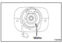
The steering wheel must be fitted correctly to the steering column with the spiral cable at the neutral position, otherwise cable disconnection and other troubles may result.
Refer to SR-37 of this manual concerning correct steering wheel installation.
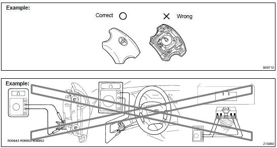
(d) STEERING WHEEL PAD (with Airbag)
- When removing the steering wheel pad or handling
a new steering wheel pad, it should be placed with
the pad top surface facing up.
Storing the pad with its metallic surface facing upward may lead to a serious accident if the airbag inflates for some reason. In addition do not store a steering wheel pad on top of another one.
- Never measure the resistance of the airbag squib.
(This may cause the airbag to deploy, which is very dangerous.)
- Grease should not be applied to the steering wheel pad and the pad should not be cleaned with detergents of any kind.
- Store the steering wheel pad where the ambient temperature remains below 93C (200F), without high humidity and away from electrical noise.
- When using electric welding, first disconnect the airbag connector (yellow color and 2 pins) under the steering column near the combination switch connector before starting work.
- When disposing of a vehicle or the steering wheel
pad alone, the airbag should be deployed using an
SST before disposal ( RS-20 ).
Carry out the operation in a safe place away from electrical noise.
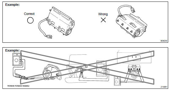
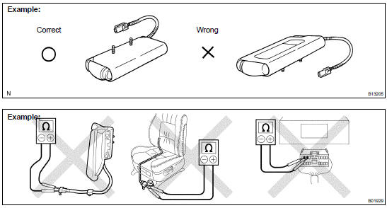
(e) FRONT PASSENGER AIRBAG ASSEMBLY
- Always store a removed or new front passenger airbag
assembly with the airbag deployment direction
facing up.
Storing the airbag assembly with the airbag deployment direction facing down could cause a serious accident if the airbag inflates.
- Never measure the resistance of the airbag squib.
(This may cause the airbag to deploy, which is very dangerous.)
- Grease should not be applied to the front passenger airbag assembly and the airbag door should not be cleaned with detergents of any kind.
- Store the airbag assembly where the ambient temperature remains below 93C (200F), without high humidity and away from electrical noise.
- When using electric welding, first disconnect the airbag connector (yellow color and 2 pins) installed on the assembly before starting work.
- When disposing of a vehicle or the airbag assembly
alone, the airbag should be deployed using an SST
before disposal ( RS-34 ).
Perform the operation in a safe place away from electrical noise.
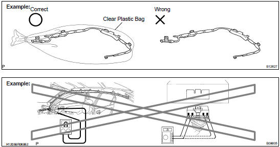
(f) SIDE AIRBAG ASSEMBLY
- Always store a removed or new side airbag assembly
with the airbag deployment direction facing up.
Storing the airbag assembly with the airbag deployment direction facing downward may lead to a serious accident if the airbag deploys for some.
- Never measure the resistance of the airbag squib reason (This may cause the airbag to deploy, which is very dangerous.).
- Grease should not be applied to the side airbag assembly and the surface should not be cleaned with detergents of any kind.
- Store the airbag assembly where the ambient temperature remains below 93C (200F), without high humidity and away from electrical noise.
- When using electric welding, first disconnect the airbag connector (yellow color and 2 pins) under the seat before starting work.
- When disposing of a vehicle or the side airbag assembly
alone, the airbag should be deployed using
an SST before disposal ( RS-48 ).
Perform the operation in a safe place away from electrical noise.
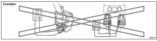
(g) CURTAIN SHIELD AIRBAG ASSEMBLY
- Always store a removed or new curtain shield airbag assembly in a clear plastic bag, and keep it in a safe place.
NOTICE: Protection bag is not reuse.
CAUTION: Never disassemble the curtain shield airbag assembly.
- Never measure the resistance of the airbag squib (This may cause the airbag to deploy, which is very dangerous.).
- Grease should not be attached to the curtain shield airbag assembly and the surface should not be cleared with detergents of any kind.
- Store the airbag assembly where the ambient temperature remains below 93 C (200 F), without high humidity and away from electrical noise.
- When using electric welding, first disconnect the airbag connector (yellow color and 2 pins) into the instrument panel before starting work.
- When disposing of a vehicle or the curtain shield airbag
assembly alone, the airbag should be deployed
using an SST before disposal ( RS-61 ).
Perform the operation in a safe place away from electrical noise.
(h) SEAT BELT PRETENSIONER
- Never measure the resistance of the seat belt pretensioner.
(This may cause the seat belt pretensioner activation which is very dangerous.)
- Never disassemble the seat belt pretensioner.
- Never install the seat belt pretensioner in another vehicle.
- Store the seat belt pretensioner where the ambient temperature remains below 80C (176F) and away from electrical noise without high humidity.
- When using electric welding, first disconnect the connector (yellow color and 2 pins) before starting work.
- When disposing of a vehicle or the seat belt pretensioner alone, the seat belt pretensioner should be activated before disposal ( BO-144 ). Perform the operation in a safe place away from electrical noise.
- The seat belt pretensioner is hot after activation, so
let it cool down sufficiently before the disposal.
However never apply water to the seat belt pretensioner.
(i) AIRBAG SENSOR ASSEMBLY
- Never reuse the airbag sensor assembly involved in a collision when the SRS has deployed.
- The connectors to the airbag sensor assembly should be connected or disconnected with the sensor mounted on the floor. If the connectors are connected or disconnected while the airbag sensor assembly is not mounted to the floor, it could cause undesired ignition of the supplemental restraint system.
- Work must be started after 90 seconds from the time the ignition switch is turned to the "LOCK" position and the negative (-) terminal cable is disconnected from the battery, even if only loosing the set bolts of the airbag sensor assembly.
(j) WIRE HARNESS AND CONNECTOR
The SRS wire harness is integrated with the instrument panel wire harness assembly. The wires for the SRS wire harness are encased in a yellow corrugated tube and all the connectors in the system are a standard yellow color.
If the SRS wire harness becomes disconnected or the connector becomes broken due to an accident, etc., repair or replace it as shown on page RS-96 .
2. FOR VEHICLE EQUIPPED WITH VEHICLE SKID CONTROL (VSC) SYSTEM
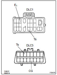
(a) Precaution when using drum tester: When using a drum tester, make sure that the ignition switch is OFF, start the engine with the diagnosis connector short-circuited between Ts and E1 (CG) and take a measurement.
NOTICE:
- Check that VSC warning light is blinking.
- Ensure that the vehicle does not move using wires.
- After the measurement, disconnect the short circuit and check that the VSC warning light is turned off when restarting the engine.
(b) Precaution during VSC operation:
- Since VSC may be affected by the removal/installation of the VSC-related parts, do not remove/install those parts unless absolutely necessary.
- When operating on VSC, follow the instructions in BR section in this manual to surely make preparations or check after operations.
3. WHEN SERVICING FULL-TIME 4WD VEHICLES
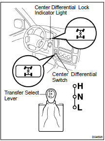
The Full-time 4WD LAND CRUISER is equipped with the mechanical lock type center differential system.
During tests using a brake tester or chassis dynamometer, such as braking force tests or speedometer tests, if only the front or rear wheels are to be rotated, it is necessary to set the position of the center differential to FREE or LOCK depending on the type of the test being performed.
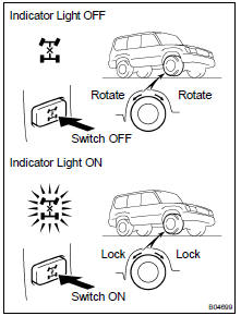
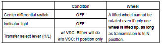
Center differential FREE condition:
Center differential LOCK conditions (w/ VSC):
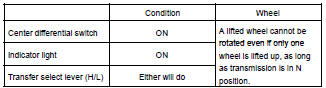
Center differential LOCK conditions (w/o VSC):
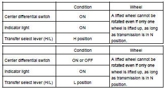
HINT: w/o Vehicle skid control (VSC) system: When the transfer select lever is put in "L" position, the center differential is put in LOCK condition regardless of the position of the center differential lock switch.
CAUTION: Center differential "LOCK" e "FREE" selecting procedure:
- Operate the switch only when all of 4 wheels are stopped or driven in a straight line.
- Never operate the switch when any wheel is slipping.
- Never operate the switch when any wheel is spinning freely.
- Never operate the switch when swerving or cornering.
HINT:
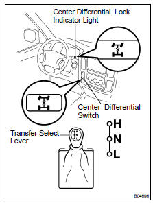
- Center differential "LOCK" e "FREE" selecting procedure: Move the vehicle forward or backward slightly if the indicator light does not operate correctly when the center differential lock switch is turned ON or OFF.
- Transfer gear "H" e "L" gear shifting procedure: When shifting, always put the shift lever of the transmission in N position. In other positions, the gears of the transfer clash, and switching cannot be performed.
4. WHEN TESTING BRAKES, SPEEDOMETER, ETC.
(a) When carrying out any kind of servicing or testing on a Full-time 4WD in which the front or rear wheels are to be rotated (braking test, speedometer test), be sure to observe the precautions given below.
Incorrect preparations or test procedures may cause danger as well as unsuccessful test results.
Before starting any such servicing or test, be sure to check the following items:
- Center differential mode position (FREE or LOCK)
- Vehicle skid control (VSC) system (with or without): If the vehicle is equipped with the system, the slip indicator light, the VSC/TRAC indicator light and the VSC OFF indicator light come on with the ignition key turned to "ON". They will go off after about a few seconds.
- Whether wheels should be touching ground or jacked up
- Transmission gear position (N position)
- Transfer gear position (H or L position)
- Maximum testing vehicle speed
- Maximum testing time
HINT: w/o Vehicle skid control (VSC) system: When the transfer select lever is put in "L" position, the center differential is put in LOCK condition regardless of the position of the center differential lock switch.
(b) Using Braking Tester: Measure by low-speed type (Vehicle Speed: Below 0.5 km/h or 0.3 mph) brake tester and observe the following instructions before performing the test.
- Position the wheels to be tested (front or rear) on the tester.
- Put the center differential in FREE position.
- If the vehicle is equipped with Vehicle Skid Control (VSC) system, prohibit the system from the activation (See step 2.).
- Shift the transmission shift lever to "N" position.
HINT: Do not forget to change the Vehicle Skid Control (VSC) & Traction Control (TRAC) system to operational condition after the test. Check that the VSC warning indicator light goes off when restarting the engine.
(c) Using Speedometer Tester: Observe the following instructions and then measure with the rear wheels.
- Position the rear wheels on the tester roller.
- Position the front wheels on the free roller or jack them up.
- Put the center differential in FREE position.
- If the vehicle is equipped with Vehicle Skid Control (VSC) & Traction Control (TRAC) system, prohibit the system from the activation (See step 2.).
- Ensure that the vehicle does not move using wires.
CAUTION: The maximum speed should be less than 60 km/h (37 mph) and maximum driving time should be 1 minute.
HINT:
- Sudden shifting, braking, acceleration or deceleration is not allowed.
- Do not forget to change the Vehicle Skid Control (VSC) & Traction Control (TRAC) system to operational condition after the test. Check that the VSC warning indicator light goes off when restarting the engine.
(d) Using Chassis Dynamometer: Observe the following instructions and then measure with the rear wheels.
- Remove the front propeller shaft.
- Put the center differential in LOCK position.
- If the vehicle is equipped with Vehicle Skid Control (VSC) & Traction Control (TRAC) system, prohibit the system from the activation (See step 2.).
- Ensure that the vehicle is securely fixed.
HINT:
- Sudden shifting, braking, acceleration or deceleration is not allowed.
- Do not forget to change the Vehicle Skid Control (VSC) & Traction Control (TRAC) system to operational condition after the test. Check that the VSC warning indicator light goes off when restarting the engine.
(e) On-V ehicle Wheel Balancing: When doing on-vehicle wheel balancing on a full-time 4WD vehicle, to prevent each wheel from being rotated at different speed in different directions (which could damage the center differential), always be sure to observe the following precautions.
- All of 4 wheels should be jacked up, being apart from the ground completely.
- Put the center differential in LOCK position.
- If the vehicle is equipped with Vehicle Skid Control (VSC) & Traction Control (TRAC) system, prohibit the system from the activation (See step 2.).
- The parking brake lever should be fully released.
- None of the brakes should be applied.
- The wheels should be driven on the wheel balancer with the engine running.
- Carry out the wheel balancing with the transmission position in D position.
HINT:
- When doing this balancing, pay attention to the other wheels rotating at the same time.
- Sudden acceleration, deceleration or braking is not allowed.
- Do not forget to change the Vehicle Skid Control (VSC) & Traction Control (TRAC) system to operational condition after the test. Check that the VSC warning indicator light goes off when restarting the engine.
5. WHEN TOWING FULL-TIME 4WD VEHICLES
- Use one of the methods shown below to tow the vehicle.
- If the vehicle has trouble in the chassis and drive train, use method 1 (flat bed truck).
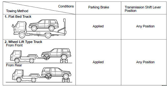
NOTICE: Do not use any towing method other than those shown above.
- For example, the towing methods shown below are dangerous or damage the vehicle, so do not use them.
|
|
Never tow the vehicle using a method where the lifted-up wheel
cannot rotate. If this towing method is used, either from the front or rear:
|
|
|
Do not use the sling type towing method, either from the front or rear, as this method causes damage to the body. |
6. FOR VEHICLES EQUIPPED WITH A CATALYTIC CONVERTER
CAUTION: If large amount of unburned gasoline flows into the converter, it may overheat and create a fire hazard.
To prevent this, observe the following precautions and explain them to your customer.
(a) Use only unleaded gasoline.
(b) Avoid prolonged idling.
Avoid running the engine at idle speed for more than 20 minutes.
(c) Avoid spark jump test.
- Perform spark jump test only when absolutely necessary. Perform this test as rapidly as possible.
- While testing, never race the engine.
(d) Avoid prolonged engine compression measurement.
Engine compression tests must be done as rapidly as possible.
(e) Do not run engine when fuel tank is nearly empty.
This may cause the engine to misfire and create an extra load on the converter.
(f) Avoid coasting with ignition turned off and prolonged braking.
(g) Do not dispose of used catalyst along with parts contaminated with gasoline or oil.
7. IF VEHICLE IS EQUIPPED WITH MOBILE COMMUNICATION SYSTEM
For vehicles with mobile communication systems such as two-way radios and cellular telephones, observe the following precautions.
- Install the antenna as far as possible away from the ECU and sensors of the vehicle's electronic system.
- Install the antenna feeder at least 20 cm (7.87 in.) away from the ECU and sensors of the vehicle's electronic systems. For details about ECU and sensors locations, refer to the section on the applicable component.
- Do not wind the antenna feeder together with the other wiring as much as possible, also avoid running the antenna feeder parallel with other wire harnesses.
- Check that the antenna and feeder are correctly adjusted.
- Do not install powerful mobile communications system.
8. FOR USING OBD II SCAN TOOL OR TOYOTA HAND-HELD TESTER
CAUTION: Observe the following items for safety reasons:
- Before using the OBD II scan tool or TOYOTA hand-held tester, the OBD II scan tool's instruction book or TOYOTA hand-held tester's operator manual should be read thoroughly.
- Be sure to route all cables securely when driving with the OBD II scan tool or TOYOTA handheld tester connected to the vehicle. (i.e. Keep cables away from feet, pedals, steering wheel and shift lever.)
- Two persons are required when test driving with the OBD II scan tool or TOYOTA hand-held tester, one person to drive the vehicle and the other person to operate the OBD II scan tool or TOYOTA hand-held tester.
For all of vehicles
How to troubleshoot ecu controlled systems
How to use the diagnostic chart and inspection
How to use this manual
Identification information
Repair instructions
Repair instructions
Vehicle lift and support locations
Toyota Land Cruiser Service Manual
Categories
