 Toyota Land Cruiser Service ManualEngine Mechanical » Timing belt
Installation
Installation
1. INSTALL CRANKSHAFT TIMING PULLEY
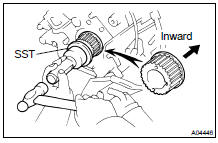
(a) Align the timing pulley set key with the key groove of the pulley.
(b) Using SST and a hammer, tap in the timing pulley, facing the flange side inward.
SST 09223-4601 1
2. INSTALL NO.1 IDLER PULLEY AND NO.2 IDLER PULLEY
(a) Apply adhesive 2 or 3 threads from the end of the pivot bolt.
Adhesive: Part No. 08833-00080, THREE BOND 1344, LOCTITE 242 or equivalent
(b) Using a 10 mm hexagon wrench, install the plate washer and the No.1 idler pulley with the pivot bolt.
Torque: 34.5 N·m (350 kgf·cm, 25 ft·lbf)
(c) Install the No.2 idler pulley with the bolt.
Torque: 34.5 N·m (350 kgf·cm, 25 ft·lbf)
(d) Check that the No.1 and No.2 idler pulley moves smoothly.
3. TEMPORARILY INSTALL TIMING BELT
NOTICE: The engine should be cold.
(a) Remove any oil or water on and clean the crankshaft pulley, the oil pump pulley, the water pump pulley, the No.1 idler pulley and the No.2 idler pulley.
NOTICE: Only wipe the pulleys; do not use any cleansing agent.
(b) Align the installation mark on the timing belt with the timing mark of the crankshaft timing pulley.
(c) Install the timing belt on the crankshaft timing pulley, the No.1 idler pulley and the No.2 idler pulley.
4. INSTALL TIMING BELT COVER SPACER
(a) Install the gasket to the cover spacer.
(b) Install the cover spacer.
5. INSTALL TIMING BELT GUIDE
Install the belt guide, facing the cup side outward.
6. INSTALL NO.1 TIMING BELT COVER
Install the timing belt cover with the 4 bolts.
7. INSTALL CRANKSHAFT PULLEY
(a) Align the pulley set key with the key groove of the crankshaft pulley.
(b) Using SST and a hammer, tap in the crankshaft pulley.
SST 09223-4601 1
8. INSTALL DRIVE BELT TENSIONER
Install the belt tensioner with the bolt and the 2 nuts.
Torque: 16 N·m (160 kgf·cm, 12 ft·lbf)
HINT: Use a bolt of 106 mm (4.18 in.) in length.
9. INSTALL GENERATOR ( CH-16 )
10. CHECK CRANKSHAFT PULLEY POSITION
Check that the timing mark of the crankshaft pulley is aligned with the timing mark "0" of the No.1 timing belt cover.
11. INSTALL RH, LH CAMSHAFT TIMING PULLEYS
(a) Align the camshaft knock pin with the knock pin grove of the timing pulley, and slide on the timing pulley.
(b) Using SST, install the pulley bolt.
SST 09960-10010 (09962-01000, 09963-01000) Torque: 108 N·m (1,100 kgf·cm, 80 ft·lbf)
12. CONNECT TIMING BELT TO LH CAMSHAFT TIMING PULLEY
(a) Remove any oil or water on the LH camshaft timing pulley, and clean it up.
NOTICE: Only wipe the pulleys; do not use any cleansing agent.
(b) Turn the LH camshaft timing pulley. Align the installation mark on the timing belt with the timing mark of the camshaft timing pulley, and hang the timing belt on the LH camshaft timing pulley.
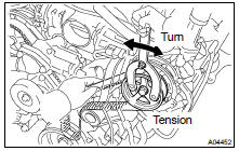
(c) Turn the LH camshaft timing pulley counterclockwise until there is tension between the crankshaft timing pulley and the LH camshaft timing pulley.
13. CONNECT TIMING BELT TO RH CAMSHAFT TIMING PULLEY
(a) Remove any oil or water on the RH camshaft timing pulley and water pump pulley, and clean them up.
NOTICE: Only wipe the pulleys; do not use any cleansing agent.
(b) Turn the RH camshaft timing pulley. Align the installation mark on the timing belt with the timing mark of the camshaft timing pulley, and hang the timing belt on the RH camshaft timing pulley.
14. SET TIMING BELT TENSIONER
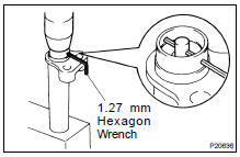
(a) Using a press, slowly press in the push rod using 981 - 9,807 N (100 - 1,000 kgf, 220 - 2,205 lbf) of pressure.
(b) Align the holes of the push rod and the housing, pass a 1.27 mm (0.050 in.) hexagon wrench through the holes to keep the setting position of the push rod.
(c) Release the press.
(d) Install the dust boot to the belt tensioner
15. INSTALL TIMING BELT TENSIONER
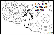
(a) Temporarily install the belt tensioner with the 2 bolts.
(b) Alternately tighten the 2 bolts.
Torque: 26 N·m (270 kgf·cm, 19 ft·lbf)
(c) Using pliers, remove the 1.27 mm (0.050 in.) hexagon wrench from the belt tensioner
16. CHECK VALVE TIMING
(a) Temporarily install the crankshaft pulley bolt.
(b) Slowly turn the crankshaft pulley 2 revolutions from TDC to TDC.
NOTICE: Always turn the crankshaft pulley clockwise.
(c) Check that each pulley aligns with the timing marks as shown in the illustration.
If the timing marks do not align, remove the timing belt and reinstall it.
17. TIGHTEN CRANKSHAFT PULLEY BOLT
Using SST, install the pulley bolt.
SST 09213-7001 1 (90105-70020), 09330-00021
Torque: 245 N·m (2,500 kgf·cm, 181 ft·lbf)
18. INSTALL FAN BRACKET
Install the fan bracket with the 2 bolts and the 2 nuts.
Torque:
12 mm head 16 N·m (160 kgf·cm, 12 ft·lbf)
14 mm head 32 N·m (330 kgf·cm, 24 ft·lbf)
HINT:
Bolt Length:
106 mm (4.17 in.) for 12 mm head (A)
114 mm (4.49 in.) for 14 mm head (B)
19. INSTALL A/C COMPRESSOR ( EM-81 )
20. INSTALL NO.2 TIMING BELT COVER
Install the No.2 timing belt cover with the 2 bolts.
Torque: 16 N·m (160 kgf·cm, 12 ft·lbf)
21. INSTALL RH NO.3 TIMING BELT COVER
(a) Fit the RH No.3 timing belt cover, matching it with the fan bracket.
(b) Install the RH No.3 timing belt cover with the 3 bolts and nut.
Torque: 7.5 N·m (80 kgf·cm, 66 in.·lbf)
22. INSTALL LH NO.3 TIMING BELT COVER
(a) Install the oil cooler pipe and the bolt.
(b) Run the camshaft position sensor wire through the LH No.3 timing belt cover hole.
(c) Fit the LH No.3 timing belt cover, matching it with the fan bracket.
(d) Install the LH No.3 timing belt cover with the 4 bolts and the nut.
Torque: 7.5 N·m (80 kgf·cm, 66 in.·lbf)
(e) Install the wire grommet to the LH No.3 timing belt cover.
(f) Install the sensor connector to the connector bracket.
(g) Connect the sensor connector.
(h) Install the sensor wire to the wire clamp on the LH No.3 timing belt cover.
(i) Install the engine wire to the 2 wire clamps on the LH No.3 timing belt cover.
23. INSTALL DRIVE BELT IDLER PULLEY
Install the idler pulley and the cover plate with the bolt.
Torque: 37 N·m (380 kgf·cm, 27 ft·lbf)
24. INSTALL RADIATOR ASSEMBLY ( CO-19 )
25. INSTALL FAN PULLEY, FAN, FLUID COUPLING AND DRIVE BELT
(a) Temporarily install the fan pulley, the fan, fluid coupling assembly with the 4 nuts.
(b) Install the generator drive belt.
( CH-16 )
(c) Tighten the 4 nuts holding the fluid coupling to the fan
bracket.
Torque: 21 N·m (215 kgf·cm, 16 ft·lbf)
26. INSTALL AIR CLEANER AND INTAKE AIR CONNECTOR ASSEMBLY
27. INSTALL V-BANK COVER
28. FILL WITH ENGINE COOLANT
29. START ENGINE AND CHECK FOR LEAKS
30. RECHECK ENGINE COOLANT LEVEL
31. INSTALL BATTERY CLAMP COVER
32. INSTALL ENGINE UNDER COVER
33. INSTALL OIL PAN PROTECTOR
Components
Inspection
Installation
Removal
Toyota Land Cruiser Service Manual
Categories
