 Toyota Land Cruiser Service ManualBrake » Disassembly
Components
Components
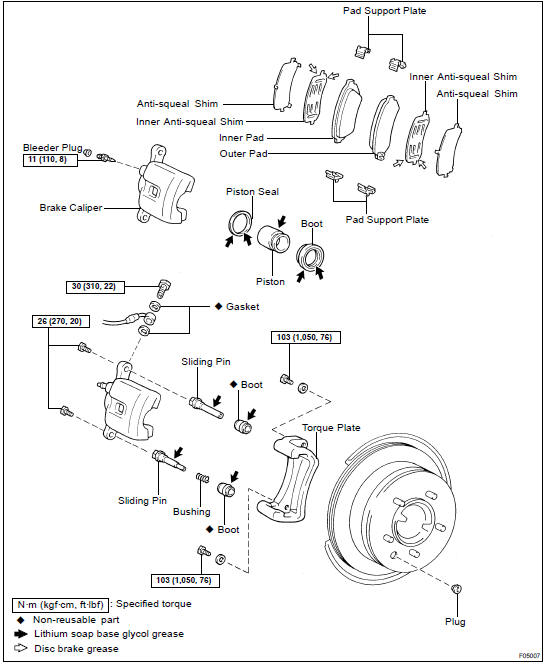
DISASSEMBLY
1. REMOVE CYLINDER BOOTS
Using a screwdriver, remove the cylinder boot from the caliper.
2. REMOVE PISTON
(a) Place a piece of cloth or a similar, object between the piston and caliper.
(b) Use compressed air to remove the piston from the cylinder.
CAUTION: Do not place your fingers in front of the piston when using compressed air.
3. REMOVE PISTON SEALS FROM BRAKE CYLINDER
Using a screwdriver, remove the piston seals from the caliper.
4. REMOVE PIN BOOT AND SLIDING BUSHING
Using a screwdriver, pull out sliding pin, pin boot and sliding bushing.
HINT: Tape the screwdriver tip before use.
NOTICE: At the time of reassembly, please refer to the following item.
Insert the sliding pin with sliding bushing into the lower part, and insert the sliding pin without sliding bushing into the upper part.
INSPECTION
1. MEASURE PAD LINING THICKNESS
Using a ruler, measure the pad lining thickness.
Standard thickness: 12.0 mm (0.472 in.) Minimum thickness: 1.0 mm (0.039 in.)
Replace the pad if the pad's thickness is at the minimum or if it shows signs of uneven wear.
2. MEASURE DISC THICKNESS
(a) Temporarily fasten the disc with the 3 hub nuts.
(b) Using a micrometer, measure the disc thickness.
Standard thickness: 18.0 mm (0.709 in.) Minimum thickness: 16.0 mm (0.611 in.)
Replace the disc if the thickness of the disc is at the minimum thickness or less. Replace the disc or grind it on a lathe if it is scored or is worn unevenly.
3. MEASURE DISC RUNOUT
Using a dial indicator, measure the disc runout at a position 10 mm (0.39 in.) from the outside edge.
Maximum disc runout: 0.1 mm (0.0040 in.)
If the disc's runout is at the maximum value or greater, check the bearing play is in the axial direction and check the axle hub runout ( SA-84 ). If the bearing play and axle hub runout are not abnormal, adjust the disc runout or grind it on an "On- Car" brake lathe.
4. IF NECESSARY, ADJUST DISC RUNOUT
(a) Remove the torque plate from the backing plate.
(b) Remove the hub nuts and the disc. Reinstall the disc rotating 1/5 of a turn from its original position on the hub.
Install and torque the hub nuts.
Torque: 103 N·m (1,050 kgf·cm, 76 ft·lbf)
Remeasure the disc runout. Make a note of the runout and the disc's position on the hub.
(c) Repeat (b) until the disc has been installed on the 3 remaining hub positions.
(d) If the minimum runout recorded in (b) and (c) is less than 0.1 mm (0.0040 in.), install the disc in that position.
(e) If the minimum runout recorded in (b) and (c) is greater than 0.1 mm (0.0040 in.), replace the disc and repeat step 3.
(f) Install the torque plate and tighten the 2 bolts.
Torque: 103 N·m(1,050 kgf·cm, 76 ft·lbf)
INSTALLATION
Installation is in the reverse order of removal ( BR-28 ).
HINT: After installation, fill the brake reservoir with brake fluid and bleed brake system ( BR-4 ).
Check for leaks
REASSEMBLY
Reassembly is in the reverse order of disassembly ( BR-29 ).
HINT: Apply lithium soap base glycol grease to the parts indicated by the arrows ( BR-27 ).
REMOVAL
1. DISCONNECT FLEXIBLE HOSE
Remove the union bolt and gasket from the caliper, then disconnect the flexible hose from the caliper. Use a container to catch brake fluid as it drains out.
Torque: 30 N·m (310 kgf·cm, 22 ft·lbf)
HINT: At the time of installation, please refer to the following item.
Install the flexible hose lock securely in the lock hole in the caliper.
2. REMOVE CALIPER
(a) Hold the sliding pin and loosen the 2 installation bolts.
Torque: 26 N·m (270 kgf·cm, 20 ft·lbf)
(b) Remove the 2 installation bolts.
(c) Remove the caliper from the torque plate.
3. REMOVE 2 BRAKE PADS WITH ANTI- SQUEAL SHIMS
4. REMOVE 4 PAD SUPPORT PLATES
Inspection
Removal
Components
Toyota Land Cruiser Service Manual
Categories
