 Toyota Land Cruiser Service ManualEngine Mechanical » Installation
Removal
Removal
1. DRAIN ENGINE COOLANT
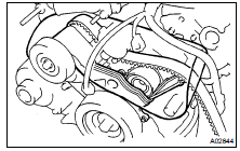
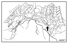
2. REMOVE V-BANK COVER
Remove the V-bank covers.
3. DISCONNECT TIMING BELT FROM CAMSHAFT TIMING PULLEYS ( EM-15 )
4. REMOVE CAMSHAFT TIMING PULLEYS ( EM-15 )
5. REMOVE CAMSHAFT POSITION SENSOR ( IG-9 )
6. DISCONNECT PS PUMP FROM ENGINE ( EM-77 )
7. REMOVE FRONT EXHAUST PIPE ( EM-1 15)
8. REMOVE OIL DIPSTICK AND GUIDE FOR A/T
9. REMOVE IGNITION COILS ( IG-6 )
10. REMOVE TIMING BELT REAR PLATES
- Remove the 3 bolts, the stud bolt, and the RH No.1 timing belt rear plates.
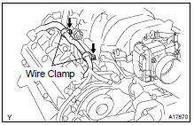
- Disconnect the wire clamp from the LH timing belt rear plate.
- Remove the 3 bolts, the stud bolt, the LH No.1 and the timing belt rear plates.
NOTICE:
- Be careful not to drop anything inside the timing belt cover.
- Do not allow the belt to contact correct with oil, water or dust.
11. DISCONNECT FUEL INLET HOSE ( SF-24 )
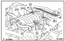
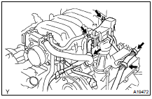
12. REMOVE INTAKE MANIFOLD ASSEMBLY
(a) Disconnect the throttle control connector.
(b) Disconnect the VSV connector for EVAP.
(c) Disconnect the 8 injector connectors.
(d) Disconnect the ECT sensor connector.
(e) Disconnect the water sender gauge connector.
(f) Disconnect the 8 ignition coil connectors.
(g) Disconnect the 2 oxygen sensor connectors.
(h) Disconnect the fuel pressure regulator vacuum hose from the fuel pressure regulator pipe.
(i) Disconnect the PCV hose from the PCV valve on the LH cylinder head.
(j) Disconnect the EVAP hose (from charcoal canister) from VSV for EVAP.
(k) Disconnect the EVAP hose (from charcoal canister) from the EVAP pipe on the intake manifold.
(l) Disconnect the EVAP hose (from intake air connector) from the EVAP pipe on the intake manifold.
(m) Disconnect the PS air hose from the intake manifold.
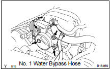
(n) Disconnect the No.1 water bypass hose from the front water by-pass joint.
(o) Disconnect the 2 wire clamps from the wire clamp bracket on the RH delivery pipe.
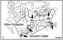
(p) Remove the 2 bolts and disconnect the engine wire protector from the rear water bypass joint and the RH cylinder head.
(q) Remove the guide for A/T bracket from the LH cylinder head.
(r) Remove the 2 ground cables from the RH and LH cylinder head.
(s) Remove the 2 bolts and disconnect the engine wire protector from the intake manifold.
(t) Remove the engine wire from the engine hanger.
(u) Remove the engine wire from the wire bracket.
(v) Remove the RH rear and the LH front V-bank cover brackets.
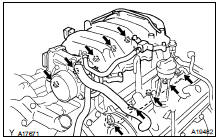
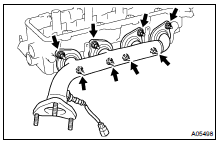
(w) Remove the 6 bolts, the 4 nuts, the intake manifold assembly and the 2 gaskets.
13. DISASSEMBLE UPPER AND LOWER INTAKE MANIFOLDS
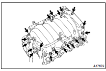
(a) Remove the throttle body ( SF-36 ).
(b) Remove the 13 bolts, the 3 nuts, the upper intake manifold and the gasket.
(c) Disconnect the EVAP hose from the upper intake manifold, and remove the accelerator cable clamp and VSV for EVAP.
(d) Remove the bolt, the union, the 2 gaskets and the brake booster tube from the upper intake manifold.
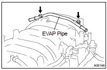
(e) Remove the 2 bolts and the EVAP pipe from the intake manifold.
(f) Disconnect the fuel return hose from the fuel pressure regulator.
(g) Remove the 3 bolts holding the fuel return hose from the lower intake manifold.
(h) Remove the fuel pressure regulator, the fuel pressure pulsation damper and the 2 gaskets.
(i) Remove the bolt and the rear fuel pipe.
(j) Remove the 2 delivery pipes and the 8 injectors ( SF-22 ).
14. REMOVE WATER INLET AND INLET HOUSING ASSEMBLY ( CO-6 )
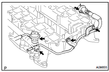
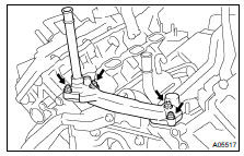
15. REMOVE FRONT WATER BYPASS JOINT
Remove the 4 nuts, the water bypass joint and the 2 gaskets.
16. REMOVE REAR WATER BYPASS JOINT
Remove the 4 nuts, the water bypass joint and the 2 gaskets.
17. REMOVE ENGINE HANGERS
18. REMOVE OIL DIPSTICK AND GUIDE FOR A/T
19. REMOVE CYLINDER HEAD COVERS
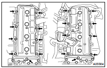
Remove the 18 bolts, the 18 seal washers, the cylinder head cover and gasket. Remove the 2 cylinder head covers.
20. IF NECESSARY, REMOVE SEMI-CIRCULAR PLUGS AND CAMSHAFT HOUSING PLUGS
21. REMOVE CAMSHAFTS
NOTICE: Since the thrust clearance of the camshaft is small, the camshaft must be kept level while it is being removed.
Otherwise, excessive pressure is put on the cylinder head journal thrust, causing a burr on the journal and damage on the camshaft. To avoid this, follow the steps below.
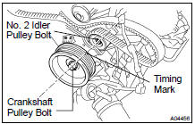
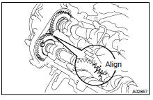
(a) Check the crankshaft pulley position.
Check that the timing mark of the crankshaft pulley is aligned with the centers of the crankshaft pulley bolt and the idler pulley bolt.
NOTICE: Having the crankshaft pulley at the wrong angle can cause the piston head and the valve head to come into contact with each other when removing the camshaft, causing damage on them. So always set the crankshaft pulley at the correct angle.
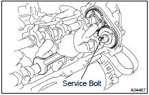
(b) Remove the RH camshafts.
- Move a service bolt of the sub-gear upward by turning the hexagon shaped port of the exhaust camshaft with a wrench.
- Secure the sub-gear to the main gear with a service bolt.
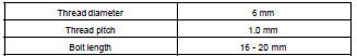
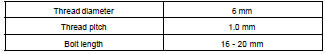
Recommended service bolt:
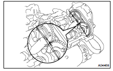
HINT: When removing the camshafts, make sure that the torsional spring force of the sub-gear is eliminated by the above operation.
- Set the timing mark (1 dot mark) of the camshaft main gear at approx. 10 angle by turning the hexagon wrench head portion of the exhaust camshaft with a wrench.
- Uniformly loosen and remove the 22 bearing cap bolts a little at a time for several times in the sequence shown.
- Remove the oil feed pipe, 9 bearing caps, cam shaft timing oil control valve and camshafts.
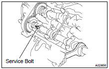
(c) Remove the LH camshafts.
- Move a service bolt of the sub-gear upward by turning the hexagon shaped port of the exhaust camshaft with a wrench.
- Secure the sub-gear to the main gear with a service bolt.
Recommended service bolt:
HINT: When removing the camshaft, make sure that the torsional spring force of the sub-gear is eliminated by the above operation.
- Align the timing mark (2 dot marks) of the camshaft drive gear by turning the hexagon wrench head portion of the exhaust camshaft with a wrench.
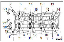
- Evenly loosen and remove the 22 bearing cap bolts a little at a time for several times as in the sequence shown.
- Remove the oil feed pipe, 9 bearing caps, and camshafts.
HINT: Arrange the bearing caps in correct order for installation.
22. DISASSEMBLE EXHAUST CAMSHAFTS
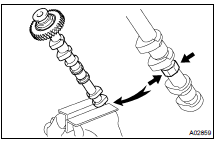
(a) Mount the hexagon wrench head portion of the camshaft in a vise.
NOTICE: Be careful not to damage the camshaft.
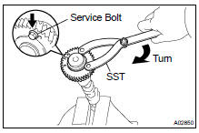
(b) Using SST, turn the sub-gear clockwise, and remove the service bolt.
SST 09960-10010 (09962-01000, 09963-00500)
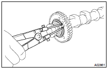
(c) Using snap ring pliers, remove the snap ring.
(d) Remove the wave washer.
(e) Remove the camshaft sub-gear.
(f) Remove the camshaft gear spring.
HINT: Arrange the camshaft sub-gears and gear spring (RH and LH sides).
NOTICE: Be careful not to damage the camshaft timing tube.
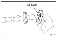
23. REMOVE OIL SEAL FROM INTAKE CAMSHAFT
24. REMOVE SPARK PLUGS
25. REMOVE CYLINDER HEAD AND EXHAUST MANIFOLD ASSEMBLIES
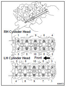
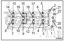
(a) Uniformly loosen the 10 cylinder head bolts on one side of each cylinder head in a little at a time for several times as in the sequence shown, then do the other side as shown. Remove the 20 cylinder head bolts and the plate washers.
NOTICE:
- Removing the bolts in incorrect order could cause a warp or cracks in the cylinder head.
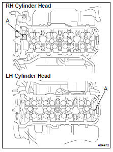
- Do not drop the plate washer of the cylinder head bolt into A area in the illustration. It will fall down to the oil pan through the cylinder head and the cylinder block.
(b) Lift the cylinder head from the dowels on the cylinder block, and place the 2 cylinder heads on wooden blocks.
HINT: After lifting off the cylinder head, pry off the cylinder head and the cylinder block with a screwdriver.
NOTICE:
- Be careful not to damage the contact surfaces of the cylinder head and the cylinder block.
- The cylinder head should not be tilted so to secure the valve lifter. If the cylinder head is tilted, remove the valve lifter and check that the adjusting shim is set correctly.
26. REMOVE RH EXHAUST MANIFOLD FROM CYLINDER HEAD
(a) Remove the 4 bolts and the heat insulator.
(b) Remove the 8 nuts, the exhaust manifold and the gasket.
27. REMOVE LH EXHAUST MANIFOLD FROM CYLINDER HEAD
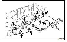
(a) Remove the 4 bolts and the heat insulator.
(b) Remove the 8 nuts, the exhaust manifold and the gasket.
Reassembly
Removal
Toyota Land Cruiser Service Manual
Categories
