 Toyota Land Cruiser Service ManualSuspension & Axle » Rear differential carrier (w/ Diff. Lock)
Reassembly
Reassembly
HINT:
- Using a shop rag, clean off any foreign object from the parts.
- Apply all of the sliding and rotating surfaces with hypoid gear oil.
1. MEASURE SIDE GEAR BACKLASH
(a) Install the 2 thrust washers to the 2 side gears.
(b) Install the 4 thrust washers to the 4 pinion gears.
(c) Install the side gear into the case.
(d) Install the holder into the case.
(e) Install the 4 pinion gears with the thrust washers.
(f) Align the holes of the differential case and pinion shaft, and install the 3 pinion shafts.
(g) Install the side gear to the cover.
(h) Align the matchmarks and install the case and cover.
(i) Using a torx socket (E10), install the 5 bolts and 3 pinion shaft pins.
Torque: 58 N·m (590 kgf·cm, 43 ft·lbf)
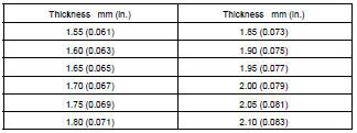
(j) Using a dial indicator, while holding the side gear, measure the backlash.
Backlash: 0.02 - 0.15 mm (0.0008 - 0.0059 in.)
If the backlash is not within the specified value, install the thrust washer of a different thickness.
HINT:
- Try to select washers of the same size for both sides.
- Measure at all 4 locations.
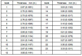
Thrust washer thickness:
(k) After measuring backlash, remove the 5 set bolts and 3 pinion shaft pins.
2. ASSEMBLE DIFFERENTIAL CASE
(a) Clean the threads of the bolts, pinion shaft pins, case and cover with the white gasoline.
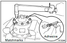
(b) Coat the threads of the bolts and pinion shaft with adhesive.
Adhesive: Part No. 08833-00070, THREE BOND 1324 or equivalent
(c) Align the matchmarks, install the case and cover.
(d) Using a torx socket (E10), install the 5 bolts and 3 pinion shaft pins.
Torque: 58 N·m (590 kgf·cm, 43 ft·lbf)
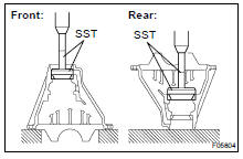
3. INSTALL SIDE BEARINGS
(a) Cover side: Using SST and a press, install the side bearing on the differential cover.
SST 09550-60010
(b) Ring gear side: Using SST and a press, install the side bearing on the differential case.
SST 09550-60010
4. INSTALL RING GEAR ON DIFFERENTIAL CASE
(a) Clean the threads of the bolts and differential case with the white gasoline.
(b) Clean the contact surfaces of the differential case and ring gear.
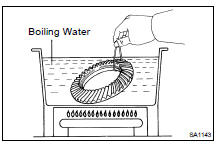
(c) Heat the ring gear to about 100 C (212 F) in boiling water.
(d) Carefully take the ring gear out of the boiling water.
(e) After the moisture on the ring gear has completely evaporated, quickly install the ring gear on the differential case.
(f) Align the matchmarks on the ring gear and differential case.
(g) Temporarily install the 12 set bolts.
(h) After the ring gear has cooled down enough, torque the 12 set bolts to which thread lock has been applied.
Thread lock: Part No.08833-00100, THREE BOND 1360K or equivalent
Torque: 137 N·m (1,400 kgf·cm, 101 ft·lbf)
5. CHECK RING GEAR RUNOUT
(a) Place the bearing outer races on their respective bearings.
Check that the right and left outer races are not interchanged.
(b) Install the assembled plate washers onto the side bearing.
(c) Install the differential case in the differential carrier.
HINT: If it is difficult to install the differential case into the carrier, replace the plate washer with a thinner one.
However, select a plate washer that allows no clearance between it and the carrier.
(d) Align matchmarks on the bearing cap and differential carrier.
(e) Install and uniformly tighten the 4 bolts a little at a time.
(f) Using a dial indicator, check the ring gear runout.
Maximum runout: 0.05 mm (0.0020 in.)
(g) Remove the differential case.
6. INSTALL DRIVE PINION FRONT AND REAR BEARING OUTER RACES
(a) Using SST and a press, install the front bearing outer race.
SST 09950-60020 (09951-00710), 09950-70010 (09951-07150)
(b) Using SST and a press, install the rear bearing outer race.
SST 09950-60020 (09951-00890), 09950-70010 (09951-07150)
7. INSTALL DRIVE PINION REAR BEARING
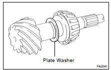
(a) Install the plate washer on the drive pinion.
HINT: First fit a washer with the same thickness as the washer which was removed, then after checking the tooth contact pattern, replace the washer with one of a different thickness if necessary.
(b) Using SST and a press, install the rear bearing onto the drive pinion.
SST 09506-35010
8. TEMPORARILY ADJUST DRIVE PINION PRELOAD
(a) Install the drive pinion and front bearing.
HINT: Assemble the spacer and oil seal after adjusting the gear contact pattern.
(b) Install the oil slinger.
(c) Install the companion flange with SST.
SST 09950- 30012 (09951- 03010, 09953- 03010, 09954-03010, 09955-03030, 09956-03040)
(d) Using SST to hold the flange and adjust the drive pinion preload by tightening the companion flange nut.
SST 09330-00021
NOTICE:
- Coat the nut and screw of the drive pinion with gear oil.
- As there is no spacer, tighten the nut a little at a time, being careful not to overtighten.

(e) Using a torque wrench, measure the preload.
Preload (at starting): New bearing 1.3 - 1.8 N·m (13 - 19 kgf·cm, 11.5 - 15.9 in.·lbf) Reused bearing 0.64 - 0.92 N·m (6.5 - 9.4 kgf·cm, 5.7 - 8.1 in.·lbf)
HINT: Measure the total preload after turning the bearing clockwise and counterclockwise several times to make the bearing smooth.
9. INSTALL DIFFERENTIAL CASE IN CARRIER
(a) Place the 2 bearing outer races on their respective bearings.
Make sure that the right and left races are not interchanged.
(b) Install the assembled plate washer onto the side bearing.
(c) Install the differential case in the carrier.
(d) Settle down the plate washer and bearing snugly by tapping on the ring gear with a plastic hammer.
HINT: If it is difficult to install the differential case into the carrier, replace the plate washer with a thinner one.
However, select a plate washer that allows no clearance between it and the carrier.
10. ADJUST RING GEAR BACKLASH
(a) Using a dial indicator, while holding the side bearing of the ring gear side measure the backlash.
Backlash (Reference): 0.15 mm (0.0059 in.)
(b) Select a cover side plate washer using the backlash as a reference.
Plate washer thickness:
(c) Select a ring gear side plate washer so that there is no clearance between the outer race and case.
(d) Remove the 2 plate washers and differential carrier.
(e) Install the plate washer into the lower part of the carrier.
(f) Place the plate washer onto the differential case together with the outer races, and install the differential case with the outer race into the carrier.
(g) Settle down the plate washer and bearing snugly by tapping on the ring gear with a plastic hammer.
(h) Using a dial indicator, measure the ring gear backlash.
Backlash: 0.13 - 0.18 mm (0.0051 - 0.0071 in.)
If it is not within the specified value, adjust it by either increasing or decreasing the thickness of washers on both sides by an equal amount.
HINT: There should be no clearance between the plate washer and case.
Ensure that there is ring gear backlash.
11. ADJUST SIDE BEARING PRELOAD
(a) After adjustment using the backlash as reference, remove the ring gear side plate washer.
(b) Using a micrometer, measure the thickness of the removed plate washer.
(c) Install a new washer 0.06 - 0.09 mm (0.0024 - 0.0035 in.) thicker than the removed washer.
HINT: Select a washer which can be pressed in 2/3 of the way with finger.
(d) Using SST, tap in the plate washer.
SST 09504-22012
(e) Align the matchmarks on the cap and carrier.
(f) Tighten the 4 bearing cap bolts to the specified torque.
Torque: 113 N·m (1,150 kgf·cm, 83 ft·lbf)
(g) Using a dial indicator, measure the ring gear backlash until it is within the specified value.
Backlash: 0.13 - 0.18 mm (0.0051 - 0.0071 in.)
If the backlash is not within the specified value, adjust by either increasing or decreasing the thickness of washers on both sides by an equal amount.
(h) After rotating the ring gear 5 turns or more, recheck the ring gear backlash.
12. MEASURE TOTAL PRELOAD
Using a torque wrench, measure the preload with the teeth of the drive pinion and ring gear in contact.
Preload (at starting): Drive pinion preload plus 0.3 - 0.5 N·m (3 - 5 kgf·cm, 2.7 - 4.4 in.·lbf)
13. INSPECT TOOTH CONTACT BETWEEN RING GEAR
(a) Coat 3 or 4 teeth at 3 different positions on the ring gear with red lead primer.
(b) Turn the companion flange, in both directions to inspect the ring gear for proper tooth contact.
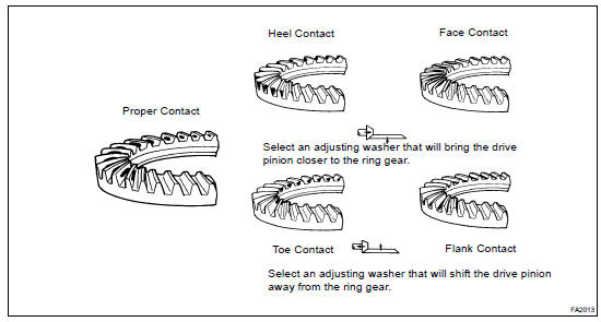
If the teeth are not contacting properly, use the following table to select a proper washer for correction.
Plate washer thickness:

14. REMOVE COMPANION FLANGE (SA-121 )
15. REMOVE OIL SLINGER AND FRONT BEARING (SA-121 )
16. REMOVE BEARING OUTER RACE
Using SST, remove the bearing outer race.
SST 09308-00010
17. INSTALL NEW BEARING SPACER
18. INSTALL BEARING OUTER RACE
Using SST and a hammer, install the bearing outer race.
SST 09316-6001 1 (09316-00011, 09316-00021)
19. INSTALL FRONT BEARING AND OIL SLINGER
20. INSTALL OIL SEAL
(a) Coat the hypoid gear oil to a new oil seal periphery.
(b) Using SST and a hammer, install the oil seal, as shown.
SST 09214-7601 1
Oil seal drive in depth: 0.5 mm (0.020 in.)
(c) Coat MP grease to the oil seal lip.
21. INSTALL COMPANION FLANGE
(a) Using SST, install the companion flange.
SST 09950- 30012 (09951- 03010, 09953- 03010, 09954-03010, 09955-03030, 09956-03040)
(b) Coat the threads of a new nut with gear oil.
(c) Using SST to hold the flange, install the nut.
SST 09330-00021
Torque: 245 N·m (2,500 kgf·cm, 181 ft·lbf)
22. ADJUST DRIVE PINION PRELOAD
Using a torque wrench, measure the preload of the backlash between the drive pinion and ring gear.
Preload (at starting): New bearing 1.3 - 1.8 N·m (13 - 19 kgf·cm, 11.5 - 15.9 in.·lbf) Reused bearing 0.64 - 0.92 N·m (6.5 - 9.4 kgf·cm, 5.7 - 8.1 in.·lbf)
If the preload is greater than the specified value, replace the bearing spacer.
If the preload is less than the specified value, retighten the nut with a force of 13 N·m (130 kgf·cm, 9 ft·lbf) at a time until the specified preload is reached.
SST 09330-00021
Torque: 441 N·m (4,500 kgf·cm, 326 ft·lbf) or less
If the maximum torque is exceeded while retightening the nut, replace the bearing spacer and repeat the preload procedure.
Do not loosen the pinion nut to reduce the preload.
23. RECHECK RING GEAR BACKLASH (SA-121 )
24. RECHECK TOOTH CONTACT BETWEEN RING GEAR AND DRIVE PINION (See step 13)
25. CHECK RUNOUT OF COMPANION FLANGE (SA-121 )
26. STAKE DRIVE PINION NUT
27. INSTALL ACTUATOR, SHIFT FORK AND SLEEVE
(a) Clean contacting surfaces of any FIPG material using gasoline or alcohol.
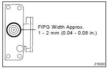
(b) Apply FIPG to the actuator.
FIPG: Part No. 08826-00090, THREE BOND 1281 or equivalent
HINT: Install the actuator within 10 minutes after applying FIPG.
(c) Install the shift fork and actuator to the differential and match the shift fork hole with the shift fork.
(d) Clean the threads of the set bolt and fork shaft with the white gasoline.
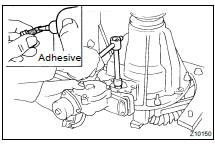
(e) Coat the threads of the set bolt with adhesive.
Adhesive: Part No. 08833-00070, THREE BOND 1324 or equivalent
(f) Install the shift fork shaft set bolt.
Torque: 20 N·m (200 kgf·cm, 15 ft·lbf)
(g) Engage the sleeve with the dog clutch of the differential case.
(h) Install the 4 bolts.
Torque: 24 N·m (240 kgf·cm, 18 ft·lbf)
28. INSTALL COVER
(a) Clean contacting surfaces of any FIPG material using gasoline or alcohol.
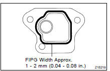
(b) Apply FIPG to the cover.
FIPG: Part No. 08826-00090, THREE BOND 1281 or equivalent
HINT: Install the cover within 10 minutes after applying FIPG.
(c) Install the cover with the 3 bolts.
Torque: 18 N·m (185 kgf·cm, 13 ft·lbf)
29. INSTALL REAR DIFF. LOCK POSITION SWITCH
Install the rear diff. lock position switch with a new gasket.
Torque: 40 N·m (410 kgf·cm, 30 ft·lbf)
30. REMOVE DIFFERENTIAL CARRIER FROM OVERHAUL STAND, ETC.
Disassembly
Installation
Reassembly
Removal
Replacement
Toyota Land Cruiser Service Manual
Categories
