 Toyota Land Cruiser Service ManualSteering » Power tilt and power telescopic steering
column
Toyota Land Cruiser Service ManualSteering » Power tilt and power telescopic steering
column
Reassembly
Reassembly
NOTICE: When using a vise, do not over tighten it.
1. COAT WITH PARTS INDICATED BY ARROWS MOLYBDENUM DISULFIDE LITHIUM BASE GREASE ( SR-27 )
2. INSTALL MAIN SHAFT ASSEMBLY
(a) Install the bearing thrust collar and compression spring to the shaft.
(b) Install the shaft assembly to the column upper tube subassembly.
(c) Using SST, compress the compression spring.
SST 09950-4001 1 (09958-04011)
NOTICE: Do not bend the universal joint of the shaft more than 20.
(d) Using a snap ring expander, install a new snap ring to the shaft.
3. INSTALL COLUMN UPPER TUBE SUB-ASSEMBLY WITH MAIN SHAFT ASSEMBLY
(a) Install the 3 bushings to the break away bracket.
(b) Install 2 new support stopper bolt bushings to the column tube assembly.
(c) Install the column upper tube assembly to the break away bracket.
(d) Install the column upper tube sub-assembly with the main shaft assembly to the break away bracket.
(e) Using a hexagon wrench, install the 2 tilt steering bolts.
Torque: 20 N·m (210 kgf·cm, 15 ft·lbf)
(f) Install a new snap ring.
4. INSTALL TELESCOPIC STEERING SCREW
(a) Install the 4 energy absorber cushions, 2 bearings and telescopic steering screw.
(b) Install the nut.
Torque: 0.8 N·m (8.2 kgf·cm, 7.1 in.·lbf)
(c) Using a punch, stake the nut.
5. INSTALL STEERING COLUMN BRACKET SPACER
6. INSTALL TELESCOPIC STEERING SLIDER
7. INSTALL TELESCOPIC STEERING BUSHING
8. INSTALL TELESCOPIC STEERING SLIDER SUPPORT
Install the telescopic steering slider support with the 2 bolts.
Torque: 11 N·m (110 kgf·cm, 8 ft·lbf)
9. INSTALL 2 ENERGY ABSORBING GUIDES, PLATES AND CLIPS
(a) Install the 2 new energy absorbing guides and 2 new absorbing plates.
(b) Install the 2 new energy absorbing clips.
10. INSTALL COLUMN TUBE SUPPORT
(a) Install the tube attachment to the column tube support.
(b) Install the column tube support with the bolt.
Torque: 15 N·m (150 kgf·cm, 11 ft·lbf)
11. INSTALL COLUMN UPPER BRACKET AND COLUMN UPPER CLAMP

(a) Install the 2 telescopic steering wedge lock springs, 2 steering lock wedges and column upper bracket and column upper clamp.
(b) Using a hexagon wrench, install the 2 telesco lever lock bolts.
Torque: 10 N·m (100 kgf·cm, 7 ft·lbf)
(c) Install and tighten the 2 new tapered-head bolts until the bolt heads break off.
(d) Install the column tube stopper.
Torque: 19 N·m (190 kgf·cm, 14 ft·lbf)
12. INSTALL POWER TELESCOPIC MOTOR
(a) Install the telescopic steering column cable.
(b) Install the power telescopic motor with the 2 bolts.
Torque: 9.0 N·m (90 kgf·cm, 78 in.·lbf)
13. INSTALL ADJUSTING NUT NO. 1
(a) Install 2 new support stopper bolt bushings to the adjusting nut No. 1.
(b) Install the adjusting nut No. 1 to the column upper tube.
(c) Install the 2 tilt steering shafts.
14. INSTALL POWER TILT MOTOR
(a) Install 2 new support stopper bolt bushings to the power tilt motor.
(b) Install 2 new E-rings.
(c) Using a hexagon wrench, install the power tilt motor and 2 tilt steering bolts.
Torque: 20 N·m (210 kgf·cm, 15 ft·lbf)
(d) Install the stopper No. 1 and stopper spring.
(e) Using a hexagon wrench, install the support stopper bolt.
15. INSTALL TURN SIGNAL BRACKET
Install the turn signal bracket with the 3 bolts.
16. INSTALL STEERING COLUMN PROTECTOR NO. 1
Install the steering column protector No. 1 with the bolt.
Torque: 15 N·m (150 kgf·cm, 11 ft·lbf)
17. INSTALL CONNECTOR BRACKET
Install the connector bracket with the bolt.
18. INSTALL TRANSPONDER KEY AMPLIFIER ASSEMBLY
19. INSTALL NO. 2 LOWER COVER
20. INSTALL INTERMEDIATE SHAFT ASSEMBLY
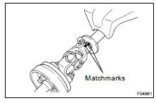
(a) Install the thrust stopper and upper side No. 2 lower cover.
(b) Align the matchmarks on the intermediate shaft assembly and main shaft assembly.
(c) Install the bolt.
Torque: 34 N·m (350 kgf·cm, 25 ft·lbf)
21. INSTALL NO. 2 LOWER COVER
Install the No. 2 lower cover with the 2 nuts.
Torque: 25 N·m (260 kgf·cm, 19 ft·lbf)
REMOVAL ( SR-14 )
Disassembly
Reassembly
Toyota Land Cruiser Service Manual
Categories
