 Toyota Land Cruiser Service ManualBody Electrical » Combination meter
Inspection
Inspection
1. INSPECT COMBINATION METER CIRCUIT
Connect the connector C12, C13, C14 and C15 to the combination meter and inspect the wire harness side connectors from the back side as shown in the table.
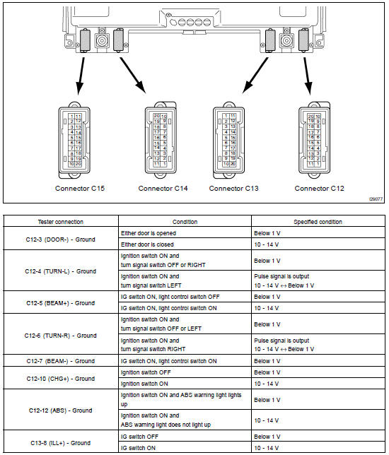
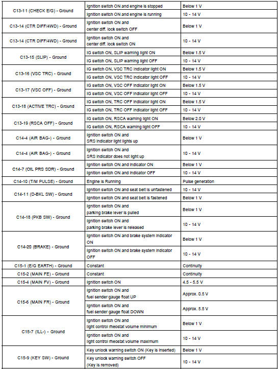
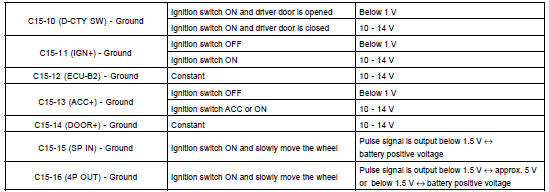
If a circuit is not as specified, inspect the applicable circuit.
2. INSPECT SPEEDOMETER/ ON-VEHICLE
Using a speedometer tester, inspect the speedometer for allowable indication error and check the operation of the odometer.
HINT: Tire wear and tire over or under inflation will increase the indication error.
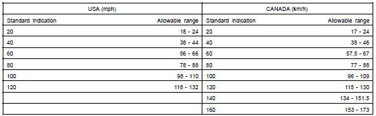
If error is excessive, replace the combination meter.
3. INSPECT SPEEDOMETER VOLTAGE
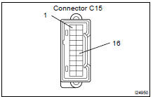
(a) While driving the vehicle at the speed of 10 km/h, check the voltage between the terminals 16 and 1 of the combination meter assy.
STANDARD: Fluctuation between 10 to 14 V or less is repeated 7 times within 1 sec.
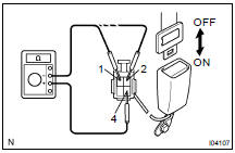
4. INSPECT VEHICLE SPEED SENSOR OPERATION
(a) Connect the positive (+) lead from the battery to terminal 1 and negative (-) lead to terminal 2.
(b) Connect the positive (+) lead from the tester to terminal 3 and the negative (-) lead to terminal 2.
(c) Rotate the shaft.
(d) Check that there is voltage change from approx. 0V to 11 V or more between terminals 2 and 3.
HINT: The voltage change should be performed 4 times for every revolution is not as specified, replace the sensor.
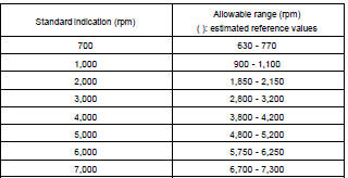
5. INSPECT TACHOMETER / ON-VEHICLE
(a) Connect a tune-up test tachometer, and start the engine.
(b) Compare the tester and tachometer indications.
DC 13.5 V 25 C at (77F):
6. INSPECT FUEL SENDER GAUGE VOLTAGE
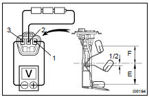
(a) Apply voltage (4.5 V - 5.0 V) between terminals 2 and 3.
(b) Measure voltage between terminals 1 and 2 for each float position.
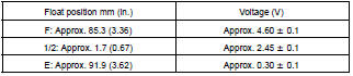
If voltage value is not as specified, replace main sender gauge.
7. INSPECT LOW OIL PRESSURE WARNING LIGHT
(a) Disconnect the connector from the low oil pressure switch.
(b) Turn the ignition switch ON.
(c) Connect the terminal of wire harness side connector and ground, then check the warning light.
8. INSPECT PARKING BRAKE WARNING LIGHT
(a) Disconnect the connector from the parking brake switch and ground terminal on the wire harness side connector.
(b) Turn the ignition switch ON and check that the warning light lights up.
9. INSPECT BRAKE WARNING LIGHT
(a) Disconnect the connector from the brake fluid level warning switch and ground terminal on the wire harness side connector.
(b) Turn the ignition switch ON and check that the warning light lights up.
10. INSPECT BRAKE FLUID LEVEL WARNING SWITCH
(a) Remove the reservoir tank cap and retainer.
(b) Disconnect the connector.
(c) Check that the continuity exists between the terminal.
(d) Use syphon, etc., to take fluid out of the reservoir tank.
(e) Check that the continuity exists between terminals.
(f) Pour the fluid back in the reservoir tank.
11. INSPECT OPEN DOOR WARNING LIGHT
(a) DIsconnect the connector from the driver door courtesy switch and ground terminal on the wire harness side connector.
(b) Turn the ignition switch ON and check that the warning light lights up.
12. INSPECT SEAT BELT WARNING BUZZER
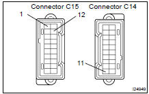
(a) Disconnect the connector from the combination meter.
(b) Connect the positive (+) lead from the battery terminal 12 and negative (-) lead terminal 1..
(c) Check that the buzzer stop after 4 to 8 seconds..
(d) Check that the buzzer stops when connecting the terminal 11 to the GND.
13. INSPECT KEY UNLOCK WARNING BUZZER
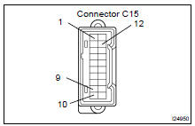
(a) Disconnect the connector from the combination meter.
(b) Connect the positive (+) lead from the battery terminal 12 and negative (-) lead terminal 1.
(c) Connect the negative (-) lead from battery terminal 9 and 10, check that the buzzer sound.
14. INSPECT SEAT BELT WARNING LIGHT
(a) DIsconnect the connector from the seat belt buckle switch and ground terminal on the wire harness side connector.
(b) Turn the ignition switch ON and check that the warning light lights up.
15. INSPECT SEAT BELT BUCKLE SWITCH CONTINUITY
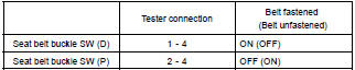
If operation is not as specified, replace the switch.
16. INSPECT SEAT BELT BUCKLE SWITCH CIRCUIT
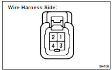
Disconnect the switch connector and inspect the connector on wire harness side, as shown.

If continuity is not as specified, inspect the ground circuit.
17. Passenger seat only: INSPECT SEAT BELT WARNING OCCUPANT DETECTION SENSOR CONTINUITY
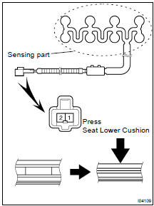
Check that continuity exists between the terminals 1 and 2 when pressing the sensing part of the lower seat cushion.
If operation is not as specified, replace the sensor.
18. INSPECT LIGHT CONTROL RHEOSTAT
(a) Turn the rheostat knob OFF, and check that there is no continuity between terminal 5 and 4 (Rheostat knob turned to fully counterclockwise).
(b) Gradually, turn the rheostat knob from the dark side to bright side, and check that there is continuity between terminal 5 and 4 (Rheostat knob turned to clockwise).
If operation is not as specified, replace the rheostat.
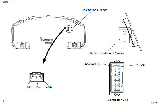
19. INSPECT INCLINATION SENSOR
(a) The inclination sensor is installed in the combination meter.
Inspect the inclination sensor by connecting a battery positive (+) lead to terminal 11 (IGN+) of the meter connector, and a battery negative (-) lead to terminal 1 (E/G EARTH).
(b) Check if the voltage between terminal Vcc and GND of the inclination sensor connector is 5 V.
(c) Check the voltage between terminal OUT and GND when the bottom surface of the inclination sensor is in a level position. Also check the voltage when it is inclined backward or forward.
Standard Value:
Bottom surface of sensor is set in a level position:
about 4.5 V
Bottom surface of sensor is inclined:
about 0.5 V
Circuit
Inspection
Toyota Land Cruiser Service Manual
Categories
