 Toyota Land Cruiser Service ManualSuspension & Axle » Rear differential carrier
Disassembly
Disassembly
1. SET DIFFERENTIAL CARRIER TO OVERHAUL STAND, ETC.
2. CHECK RUNOUT OF COMPANION FLANGE
Using a dial indicator, measure the vertical and lateral runout of the companion flange.
Maximum runout: 0.10 mm (0.0039 in.)
If the runout is greater then the maximum, replace the companion flange.
3. CHECK RING GEAR RUNOUT
Using a dial indicator, while holding the drive pinion flange, measure the ring gear runout.
Maximum runout: 0.05 mm (0.0020 in.)
If the runout is greater than the maximum, replace the ring gear.
4. CHECK RING GEAR BACKLASH
Using a dial indicator, measure the ring gear backlash.
Backlash: 0.13 - 0.18 mm (0.0051 - 0.0071 in.)
HINT: Perform the measurements at 3 or more positions around the circumference of the ring gear.
If the backlash is not within the specified value, adjust the side bearing preload or repair as necessary.
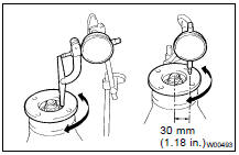
5. MEASURE DRIVE PINION PRELOAD
Using a torque wrench, measure the drive pinion preload using the backlash of the drive pinion and ring gear.
Preload (at starting): 0.64 - 0.92 N·m (6.5 - 9.4 kgf·cm, 5.7 - 8.1 in.·lbf)
6. CHECK TOTAL PRELOAD
Using a torque wrench, measure the total preload with the teeth of the drive pinion and ring gear in contact.
Total preload (at starting): Drive pinion preload plus 0.38 - 0.63 N·m (3.9 - 6.5 kgf·cm, 3.3 - 5.6 in.·lbf)
If necessary, disassemble and inspect the differential.
7. CHECK TOOTH CONTACT BETWEEN RING GEAR AND DRIVE PINION (SA-107 )
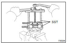
8. REMOVE COMPANION FLANGE
(a) Using a chisel and hammer, unstake the nut.
(b) Using SST to hold the flange, remove the nut.
SST 09330-00021
(c) Using SST, remove the companion flange.
SST 09950- 30012 (09951- 03010, 09953- 03010, 09954-03010, 09955-03030, 09956-03040)
9. REMOVE OIL SEAL AND OIL SLINGER
(a) Using SST, remove the oil seal from the differential carrier.
SST 09308-10010
(b) Remove the oil slinger.
10. REMOVE FRONT BEARING
Using SST, remove the front bearing from the drive pinion.
SST 09556-22010
If the front bearing is damaged or worn, replace the bearing.
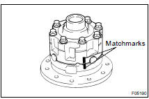
11. REMOVE DIFFERENTIAL CASE ASSEMBLY
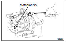
(a) Place matchmarks on the bearing cap and differential carrier.
(b) Remove the 2 bolts and adjusting nut locks.
(c) Remove the 4 bolts, 2 bearing caps and adjusting nuts.
HINT: Tag the disassembled parts to show the location for reassembling.
(d) Remove the differential case with the bearing outer races from the carrier.
HINT: Tag the disassembled parts to show the location for reassembling.
12. REMOVE DRIVE PINION AND BEARING SPACER FROM DIFFERENTIAL CARRIER
(a) Remove the drive pinion with the rear bearing.
(b) Remove the bearing spacer.
13. REMOVE DRIVE PINION REAR BEARING
(a) Using SST and a press, remove the rear bearing from the drive pinion.
SST 09950-00020
HINT: If the drive pinion or ring gear is damaged, replace them as a set.
(b) Remove the plate washer from the drive pinion.
14. REMOVE FRONT AND REAR BEARING OUTER RACES
Using a brass bar and hammer, remove the outer races.
15. REMOVE RING GEAR
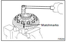
(a) Place matchmarks on the ring gear and differential case.
(b) Remove the 12 ring gear set bolts.
(c) Using a plastic hammer, tap on the ring gear to remove it from the differential case.
16. CHECK DIFFERENTIAL CASE RUNOUT
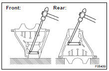
(a) Place the bearing outer races on their respective bearings.
Check that the right and left outer races are not interchanged.
(b) Install the differential case in the differential carrier.
(c) Tighten the adjusting nut just to where there is no play in the bearing.
(d) Align the matchmarks on the bearing cap and differential carrier.
(e) Install and uniformly tighten the 4 bearing cap bolts a little at a time.

(f) Using a dial indicator, measure the differential case runout.
Maximum case runout: 0.04 mm (0.0016 in.)
(g) Remove the differential case.
17. REMOVE SIDE BEARINGS FROM DIFFERENTIAL CASE
Using SST, remove the 2 side bearings from the differential case.
SST 09950-00020, 09950-00030, 09950-4001 1 (09957-04010), 09950-60010 (09951-00480)
18. DISASSEMBLE DIFFERENTIAL CASE
(a) Place matchmarks on the RH and LH differential cases.
(b) Remove the 8 bolts uniformly, a little at a time.
(c) Using a plastic hammer, separate the RH and LH differential cases.
(d) Remove the 2 side gear thrust washers, 2 side gears, spider, 4 pinion gears and pinion gear thrust washers.
INSTALLATION
Installation is in the reverse order of removal (SA-100 ).
HINT: After installation, fill the differential with hypoid gear oil (SA-95 ), fill the brake reservoir with brake fluid, bleed the brake system (BR-4 ), check for leaks and check the ABS speed sensor signal (DI-505 ).
Disassembly
Reassembly
Removal
Replacement
Toyota Land Cruiser Service Manual
Categories
