 Toyota Land Cruiser Service ManualBody Electrical » Audio system
Troubleshooting
Troubleshooting
1. DIAGNOSIS FUNCTION (Main AVC-LAN)
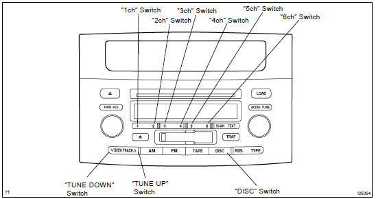
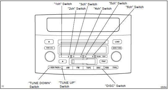
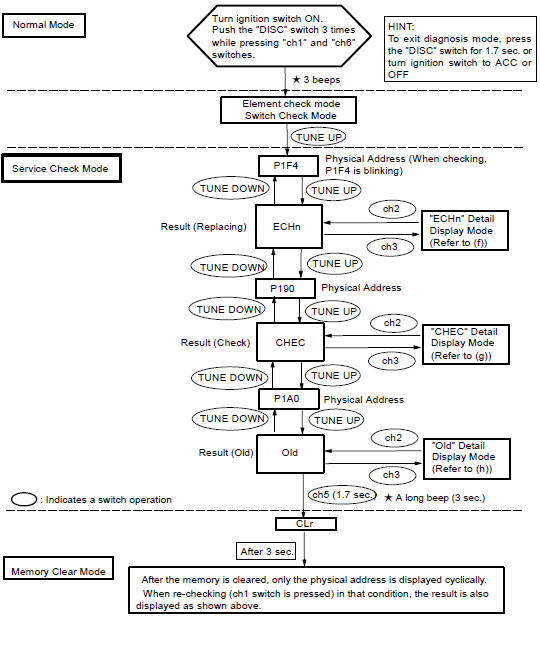
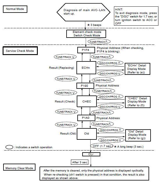
(a) Diagnosis start-up For shifting to diagnosis mode, turn the ignition switch ON and push the "DISC" switch 3 times while pressing "ch1" and "ch6" switches.
HINT: To exit the diagnosis mode, push the "DISC" switch for 1.7 sec. or turn the ignition switch to ACC or OFF. (b) Element check mode After the diagnosis start-up, the system enters the element check mode. Check that the all elements light up.
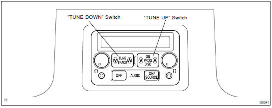
HINT: By pressing the "TUNE UP" switch, the system enters the "Service Check Mode". (c) Switch check mode
- Element check mode is started at the same time with the switch check mode.
- Check that there is a beep sound when any switch is pressed.
HINT: By pressing "TUNE UP" switch, the system enters the "Service Check Mode".
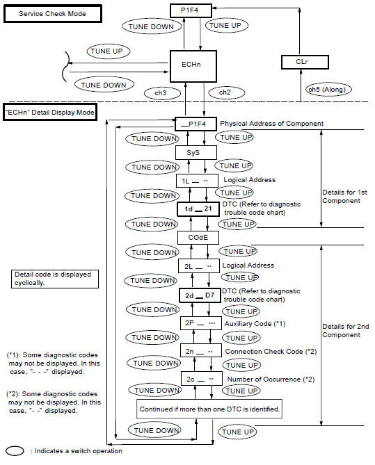
(d) Service check mode
- After the element check and switch check is completed, the system enters service check mode when "TUNE UP" switch is pressed.
- Error codes over the tuner and connected equipments are displayed on the screen of the tuner.
Results for each check are displayed as follows:
- good: No DTC is detected for both "System Check Confirmation" and "Diagnosis Memory Response".
- nCon:
The component does not respond to the "Diagnosis On Instruction" command.
Applicable to only the system where connected components are limited to be used.
- ECHn: Application of new version has been confirmed by the "Diagnosis On Check", and there is one or more DTC which indicates "Replacement" in the "System Check Result Response" or "Diagnosis Memory Response".
- CHEC: Application of new version has been confirmed by the "Diagnosis On Check", and there is no DTC which indicates "Replacement" in the "System Check Result Response" or "Diagnosis Memory Response", but one or more DTC which indicates "Check" is identified.
- Old: Application of old version is confirmed by the "Diagnosis On Check", and DTC is identified in the "System Check Result Response" or "Diagnosis Memory Response".
- nrES: No response is identified to the "System Check Start Instruction" and "Request for System Check Result" commands.
HINT:
- Check the present and past condition of components by performing the System Check and collecting stored DTC memories.
- Check results are displayed as one of the following six indications: "good", "ECHn", "CHEC","nCon", "Old" or "nrES".
(e) Display Screen for Service Check.
Example: Connection parts ( physical address): Radio receiver (P190), RSA ECU (P1F4), DVD player (P1A0)
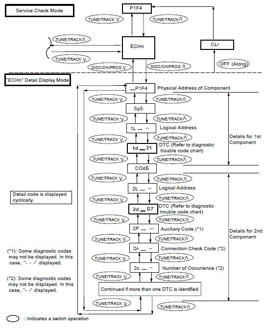
(f) "ECHn" Detail Display Mode Screen
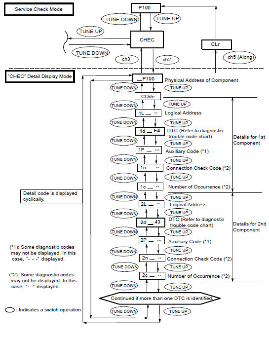
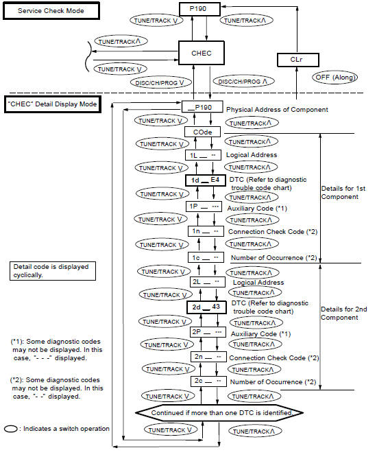
(g) "CHEC" Detail Display Mode Screen
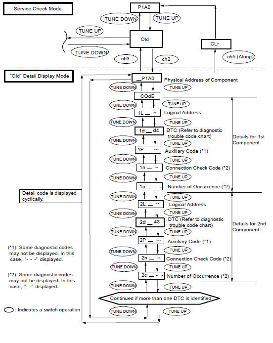
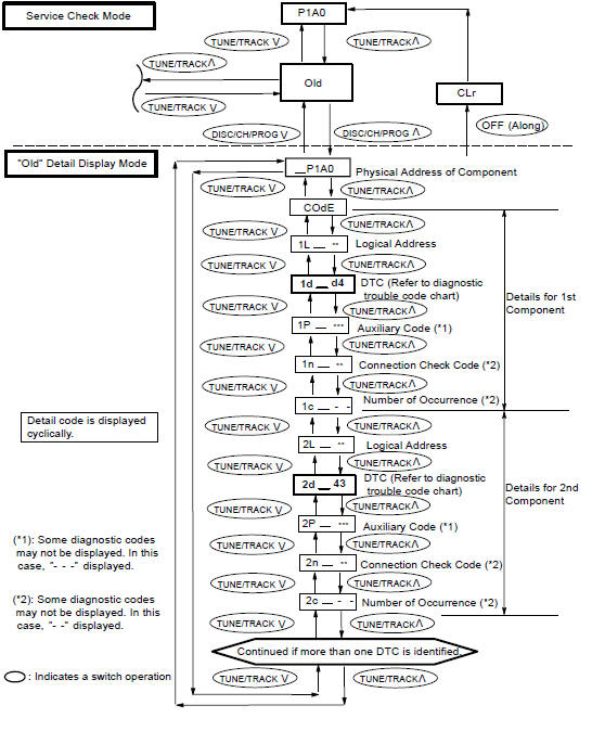
(h) "Old" Detail Display Mode Screen
2. DIAGNOSIS FUNCTION (Sub AVC-LAN)
HINT: As starting Main AVC-LAN to operate the diagnosis mode, Sub AVC-LAN is automatically to the mode. Perform the diagnosis mode operation on the RSA panel. (a) Element check mode After the diagnosis start-up, the system enters the element check mode. Check that the all elements light up.
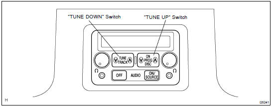
HINT: By pressing the "TUNE UP" switch, the system enters the "Service Check Mode". (b) Switch check mode
- Element check mode is started at the same time with the switch check mode.
- Check that there is a beep sound when any switch is pressed.
HINT: By pressing "TUNE UP" switch, the system enters the "Service Check Mode".
(c) Service check mode
- After the element check and switch check is completed, the system enters service check mode when "TUNE UP" switch is pressed.
- Error codes over the tuner and connected equipments are displayed on the screen of the tuner.
Results for each check are displayed as follows:
- good: No DTC is detected for both "System Check Confirmation" and "Diagnosis Memory Response".
- nCon:
The component does not respond to the "Diagnosis On Instruction" command.
Applicable to only the system where connected components are limited to be used.
- ECHn: Application of new version has been confirmed by the "Diagnosis On Check", and there is one or more DTC which indicates "Replacement" in the "System Check Result Response" or "Diagnosis Memory Response".
- CHEC: Application of new version has been confirmed by the "Diagnosis On Check", and there is no DTC which indicates "Replacement" in the "System Check Result Response" or "Diagnosis Memory Response", but one or more DTC which indicates "Check" is identified.
- Old: Application of old version is confirmed by the "Diagnosis On Check", and DTC is identified in the "System Check Result Response" or "Diagnosis Memory Response".
- nrES: No response is identified to the "System Check Start Instruction" and "Request for System Check Result" commands.
HINT:
- Check the present and past condition of components by performing the System Check and collecting stored DTC memories.
- Check results are displayed as one of the following six indications: "good", "ECHn", "CHEC","nCon", "Old" or "nrES".
(d) Display Screen for Service Check.
Example: Connection parts ( physical address): Radio receiver (P190), RSA ECU (P1F4), DVD player (P1A0)
(e) "ECHn" Detail Display Mode Screen
(f) "CHEC" Detail Display Mode Screen
(g) "Old" Detail Display Mode Screen
3. DIAGNOSIS CODE LIST
w/ Navigation system ()
Physical address: 190 Radio receiver assembly
HINT:
*1: Even if no failure is detected, it may be stored depending on the battery
condition or voltage for starting an engine.
*2: It may be stored when the engine key is turned 1 min. angain after engine
start.
*3: It may be stored when the engine key is turned again after engine start.
*4: When 210 sec. has passed after pulling out the power supply connector of the
master component with the ignition
switch in ACC or ON, this code is stored.
|
Logical address |
DTC |
Diagnosis item |
Diagnosis content |
Countermeasure and inspected parts |
| 01 (Communication Control) | 21 | ROM Error | Error is detected in internal ROM. | Replace radio receiver assembly |
| 01 (Communication Control) | 22 | RAM Error | Error is detected in internal RAM. | Replace radio receiver assembly. |
| 01 *2 (Communication Control) | D6 | Absence of Master | Component in which this code is recorded
has been disconnected from
system with ignition in ACC or ON. Or, when this code was recorded, radio receiver assembly was disconnected. |
|
| 01 *3 (Communication Control) | D8 | No Response to Connection Check | Component shown by auxiliary code
is or had been disconnected from
system after engine start. D9 |
|
| 01 *2 (Communication Control) | D9 | Last Mode Error | Component operated (sounds and/ or images were provided) before engine stop is or has been disconnected with ignition switch in ACC or ON |
|
| 01 (Communication Control) | DA | No Response to ON/OFF Instruction | No response is identified when changing mode (audio and visual mode change). Detected when sound and picture does not change by button operation |
|
| 01 *2 (Communication Control) | DB | Mode Status Error | Dual alarm is detected |
|
| 01 *4 (Communication Control) | DC | Transmission Error | Transmission to component shown
by auxiliary code has been failed. (Detecting this DTC does not necessary mean actual failure.) |
|
| 01 *3 (Communication Control) | DD | Master Reset (Momentary Interruption) | After engine is started, radio receiver assembly assembly was disconnected from system. |
|
| 01 *3 (Communication Control) | DE | Slave Reset (Momentary Interruption) | After engine is started, slave component was disconnected from system. |
|
| 01 *4 (Communication Control) | DF | Master Error | Due to defective condition of radio
receiver assembly, master function
is switched to audio equipment. Error occurs in communication between sub-master (audio) and radio receiver assembly. |
|
| 01 (Communication Control) | E0 | Registration Completion Instruction Error | "Registration Completion Instruction" command from radio receiver assembly cannot be received. |
|
| 01 *2 (Communication Control) | E1 | Audio processor ON error | While source equipment is operating, AMP output is stopped. |
|
| 01 (Communication Control) | E2 | ON/OFF Instruction Parameter Error | Error occurs in ON/OFF controlling command from radio receiver assembly assembly |
|
| 01 (Communication Control) | E3 | Registration Request Transmission | Registration Request command is
output from slave component. Receiving Connection Check Instruction, Registration Request command is output from sub-master component. |
|
| 01 (Communication Control) | E4 | Plural Frame Abort | Plural frame transmission is aborted |
|
| 60 (Radio receiver assembly) | 43 | AM Tuner Error | Abnormal condition is detected in
AM tuner. Inspect radio receiver assembly. |
Replace radio receiver assembly. |
| 60 (Radio receiver assembly) | 44 | FM Tuner Error | Abnormal condition is detected in FM tuner. | Replace radio receiver assembly. |
| 61 (Cassette switch) | 40 | Mechanical or Media Error | Malfunction due to mechanical fail- ure is identified. Or, cassette tape is cut or entangled. | Inspect cassette tape. |
| 61 (Cassette switch) | 41 | EJECT Malfunction | Malfunction due to mechanical failure. | Replace radio receiver assembly |
| 63 (In-dash CD auto changer) | 42 | No Disc Readout | Disc cannot be read. | Inspect CD. |
| 63 (In-dash CD auto changer) | 44 | CD Error | Error is detected in CD auto changer. | Replace radio receiver assembly |
| 63 (In-dash CD auto Changer) | 45 | EJECT Error | CD cannot be ejected. | Replace radio receiver assembly. |
| 63 (In-dash CD auto Changer) | 47 | CD High Temp | High temperature is detected in CD auto changer | Replace radio receiver assembly. |
| 63 (In-dash CD auto Changer) | 48 | CD Excess Current | Excess current is applied to CD auto changer. | Replace radio receiver assembly |
Physical address: 440 Strereo component amplifier
HINT:
*1: Even if no failure is detected, it may be stored depending on the battery
condition or voltage for starting an engine.
*2: It may be stored when the engine key is turned 1 min. angain after engine
start.
*3: It may be stored when the engine key is turned again after engine start.
*4: When 210 sec. has passed after pulling out the power supply connector of the
master component with the ignition
switch in ACC or ON, this code is stored.
|
Logical address |
DTC |
Diagnosis item | Diagnosis content | Countermeasure and inspeced parts |
| 01 (Communication Control) | 21 | ROM Error | Abnormal condition of ROM is detected. | Replace stereo component amplifier. |
| 01 (Communication Control) | 22 | RAM Error | Abnormal condition of RAM is detected. | Replace stereo component amplifier |
| 01 (Communication Control) | D6 *1 | Absence of Master | Component in which this code is recorded
has been disconnected from
system with ignition in ACC or ON. Or, when this code was recorded, radio receiver assembly was disconnected. |
|
| 01*6 (Communication Control) | D7 | Connection Check Error | Component in which this code is recorded
has been disconnected from
system after engine start. Or, when this code was recorded, radio receiver assembly was disconnected. |
|
| 01 (Communication Control) | DC *2 | Transmission Error | Transmission to component shown
by auxiliary code has bee failed. (This code does not necessarily mean actual failure.) |
If same auxiliary code is recorded in other component(s), check harness for power supply and communication system of components shown sub code. |
| 01 (Communication Control) | DD *3 | Master Reset (Momentary Interruption) | After engine is started, radio receiver assembly assembly was disconnected from system |
|
| 01 (Communication Control) | DF *4 | Master Error | Due to defective condition of component with a display, master function is switched to audio equipment . Error occurs in communication between sub-master (audio) and master component. |
|
| 01 (Communication Control) | E0 *1 | Registration Completion Instruction Error | "Registration Completion Instruction" command fromradio receiver assembly cannot be received. | Since this DTC is provided for engineering, it may be detected when no actual failure exists. |
| 01 (Communication Control) | E1 *1 | Audio processor ON error | While source equipment is operating, AMP output is stopped |
|
| 01 (Communication Control) | E2 | ON/OFF Instruction Parameter Error | Error is detected in ON/OFF control command from radio receiver assembly. | Replace radio receiver assembly |
| 01 (Communication Control) | E3 | Registration Request Transmission |
|
Since this DTC is provided for engineering, it may be detected when no actual failure exists. |
| 01 (Communication Control) | E4 | Plural Frame Abort | Plural frame transmission is aborted. | Since this DTC is provided for engineering purpose, it may be detected when no actual failure exists |
Physical address: 1F4 RSA Panel (Main AVC-LAN)
HINT:
*1: Even if no failure is detected, it may be stored depending on the battery
condition or voltage for starting an engine.
*2: It may be stored when the engine key is turned 1 min. angain after engine
start.
*3: It may be stored when the engine key is turned again after engine start.
*4: When 210 sec. has passed after pulling out the power supply connector of the
master component with the ignition
switch in ACC or ON, this code is stored.
|
Logical address |
DTC |
Diagnosis item |
Diagnosis content |
Countermeasure and inspeced parts |
| 01 (Communication Control) | D6 *1 | Absence of Master | Component in which this code is recorded
has been disconnected from
system with ignition in ACC or ON. Or, when this code was recorded, radio receiver assembly was disconnected. |
|
| 01*6 (Communication Control) | D7 | Connection Check Error | Component in which this code is recorded
has been disconnected from
system after engine start. Or, when this code was recorded, radio receiver assembly was disconnected. |
|
| 01 (Communication Control) | DC *2 | Transmission Error | Transmission to component shown
by auxiliary code has bee failed. (This code does not necessarily mean actual failure.) |
If same auxiliary code is recorded in other component(s), check harness for power supply and communication system of components shown sub code. |
| 01 (Communication Control) | DD *3 | Master Reset (Momentary Interruption) | After engine is started, radio receiver assembly was disconnected from system. |
|
| 01 (Communication Control) | DF *4 | Master Error | Due to defective condition of component with a display, master function is switched to audio equipment . Error occurs in communication between sub-master (audio) and master component |
|
| 01 (Communication Control) | E0 *1 | Registration Completion Instruction Error | "Registration Completion Instruction" command fromradio receiver assembly cannot be received. | Since this DTC is provided for engineering, it may be detected when no actual failure exists. |
| 01 (Communication Control) | E3 | Registration Request Transmission |
|
Since this DTC is provided for engineering, it may be detected when no actual failure exists. |
| 01 (Communication Control) | E4 | Plural Frame Abort | Plural frame transmission is aborted | Since this DTC is provided for engineering purpose, it may be detected when no actual failure exists. |
Physical address: 16A, 16C RSA Panel (Sub AVC-LAN)
HINT:
*1: Even if no failure is detected, it may be stored depending on the battery
condition or voltage for starting an engine.
*2: It may be stored when the engine key is turned 1 min. angain after engine
start.
*3: It may be stored when the engine key is turned again after engine start.
*4: When 210 sec. has passed after pulling out the power supply connector of the
master component with the ignition
switch in ACC or ON, this code is stored.
|
Logical address |
DTC |
Diagnosis item | Diagnosis content | Countermeasure and inspeced parts |
| 01 *3 (Communication Control) | D8 | No Response to Connection Check | Component shown by auxiliary code
is or had been disconnected from
system after engine start. D9 |
|
| 01 *2 (Communication Control) | D9 | Last Mode Error | Component operated (sounds and/ or images were provided) before engine stop is or has been disconnected with ignition switch in ACC or ON. |
|
| 01 (Communication Control) | DA | No Response to ON/OFF Instruction | No response is identified when changing mode (audio and visual mode change). Detected when sound and picture does not change by button operation |
|
| 01 *2 (Communication Control) | DB | Mode Status Error | Dual alarm is detected. |
|
| 01 *4 (Communication Control) | DC | Transmission Error | Transmission to component shown
by auxiliary code has been failed. (Detecting this DTC does not necessary mean actual failure.) |
|
| 01 *3 (Communication Control) | DE | Slave Reset (Momentary Interruption) | After engine is started, slave component was disconnected from system. |
|
| 01 (Communication Control) | E4 | Plural Frame Abort | Plural frame transmission is aborted. | Since this DTC is provided for engineering purpose, it may be detected when no actual failure exists. |
Physical address: 1A0 DVD Auto Player
HINT: *1: Even if no failure is detected, this code may be stored depending on the battery condition or voltage for starting an engine.> *2: This code may be stored when the engine key is turned again 1 min. after engine start.> *3: This code may be stored when the engine key is turned again after engine start.> *4: When 210 sec. has passed after pulling out the power supply connector of the master component with the ignition switch in ACC or ON, this code is stored.
|
Logical address |
DTC |
Diagnosis item |
Diagnosis content |
Countermeasure and inspeced parts |
| 01 (Communication Control) | D6 *1 | Absence of Master | Component in which this code is recorded
has been disconnected from
system with ignition in ACC or ON. Or, when this code was recorded, RSA Panel was disconnected. |
|
| 01 (Communication Control) | D7 | Communication Check Error | Component in which this code is recorded is was disconnected from system after engine start. Or, when recorded this code, RSA Panel was disconnected. |
|
| 01 *4 (Communication Control) | DC | Transmission Error | Transmission to component shown by sub-code has been failed. (Detecting this DTC does not necessary mean actual failure.) |
|
| 01 (Communication Control) | DD *3 | Master Reset (Momentary Interruption) | After engine is started, radio receiver assembly assembly was disconnected from system. |
|
| 01 (Communication Control) | DF *4 | Master Error | Due to defective condition of component with a display, master function is switched to audio equipment . Error occurs in communication between sub-master (audio) and master component. |
|
| 01 (Communication Control) | E0 *1 | Registration Completion Instruction Error | "Registration Completion Instruction" command from master cannot be received. | Since this DTC is provided for engineering purpose, it may be detected when no actual failure exists. |
| 01 (Communication Control) | E2 | ON/OFF Instruction Parameter Error | Error is detected in ON/OFF control command from DVD player. | Replace DVD player. |
| 01 (Communication Control) | E3 | Registration Request Transmission |
|
Since this DTC is provided for engineering, it may be detected when no actual failure exists. |
| 01 (Communication Control) | E4 | Multiple Frame Abort | Multiple frame transmission is aborted. | Since this DTC is provided for engineering purpose, it may be detected when no actual failure exists. |
| 01 (Communication Control) | 22 | RAM Error | Abnormal condition of RAM is detected. | Replace DVD player. |
Physical address: 250 (DVD Auto Changer) (Sub AVC-LAN)
|
Logical address |
DTC |
Diagnosis item | Diagnosis content |
Countermeasure and inspeced parts |
| 01 (Communication Control) | D6 *1 | Absence of Master | Component in which this code is recorded
has been disconnected from
system with ignition in ACC or ON. Or, when this code was recorded, radio receiver assembly was disconnected. |
|
| 01*6 (Communication Control) | D7 | Connection Check Error | Component in which this code is recorded
has been disconnected from
system after engine start. Or, when this code was recorded, radio receiver assembly was disconnected. |
|
| 01 (Communication Control) | DC *2 | Transmission Error | Transmission to component shown
by auxiliary code has bee failed. (This code does not necessarily mean actual failure.) |
If same auxiliary code is recorded in other component(s), check harness for power supply and communication system of components shown sub code. |
| 01 (Communication Control) | DD *3 | Master Reset (Momentary Interruption) | After engine is started, radio receiver assembly assembly was disconnected from system. |
|
| 01 (Communication Control) | DF *4 | Master Error | Due to defective condition of component with a display, master function is switched to audio equipment . Error occurs in communication between sub-master (audio) and master component |
|
| 01 (Communication Control) | E0 *1 | Registration Completion Instruction Error | "Registration Completion Instruction" command fromradio receiver assembly cannot be received. | Since this DTC is provided for engineering, it may be detected when no actual failure exists. |
| 01 (Communication Control) | E2 | ON/OFF Instruction Parameter Error | Error is detected in ON/OFF control command from radio receiver assembly. | Replace radio receiver assembly |
| 01 (Communication Control) | E3 | Registration Request Transmission |
|
Since this DTC is provided for engineering, it may be detected when no actual failure exists. |
| 45 (DVD) | 42 | No Disk Readout | Disk cannot be read. | Inspect disk. |
| 45 (DVD) | 44 | DVD error | Error is detected in DVD player | Replace radio and player |
| 45 (DVD) | 45 | EJECT error | Disk cannot be ejected | Check whether foreign matters enter inspection. |
| 45 (DVD) | 46 | Disk Crack | A crack and dirt are in a disk. | Inspect disk. |
| 45 (DVD) | 52 | Player Error | Clamp unusually generating | DVD player. |
| 45 (DVD) | 47 | DVD High Temp | High temperature is detected in DVD auto changer | Do not stop the operation for a period of time. |
| 45 (DVD) | 48 | DVD Excess Current | Excess current is applied to DVD auto changer | Replace DVD auto changer |
| 45 (DVD) | 50 | A Malfunction in insertion/ejection | Operation malfunction in insertion/ ejection | Replace DVD auto changer |
| 45 (DVD) | 51 | A Malfunction in switching disk | Operation malfunction in switching disk. | Replace DVD auto changer. |
4. PROBLEM SYSMPTOMS TABLE
NOTICE: When replacing the internal mechanism (computer part) of the audio system, be careful that no part of your body or clothing comes in contact with the terminals of the leads from the IC, etc. of the replacement part (spare part).
HINT: This inspection procedure is a simple troubleshooting which should be carried out on the vehicle during system operation and was prepared on the assumption of system component troubles (except for the wires and connectors, etc.).
Always inspect the trouble taking the following items into consideration.
- Open or short circuit of the wire harness
- Connector or terminal connection fault
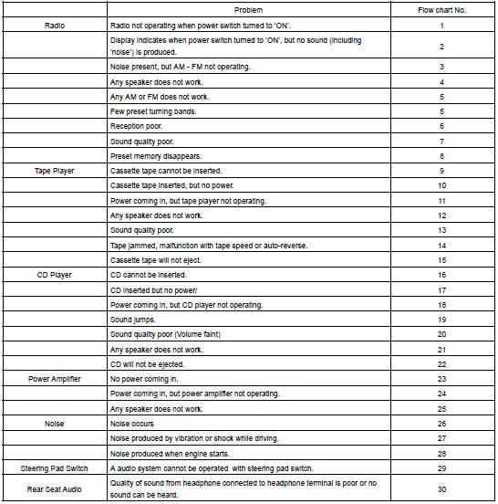
The term "AM" includes LW,MW and SW, and the term "FW" includes UKW.
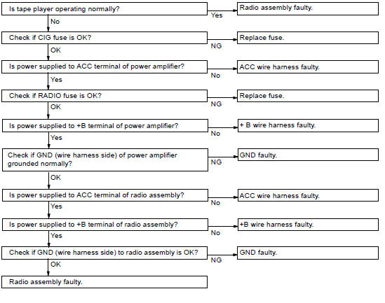
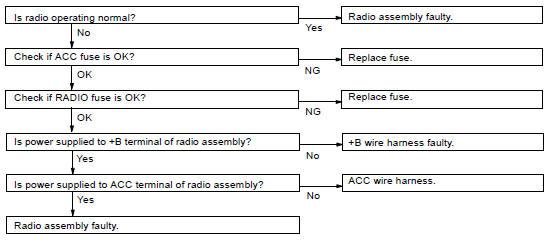
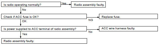
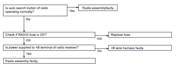
1 Radio RADIO NOT OPERATING WHEN POWER SWITCH TURNED TO "ON"
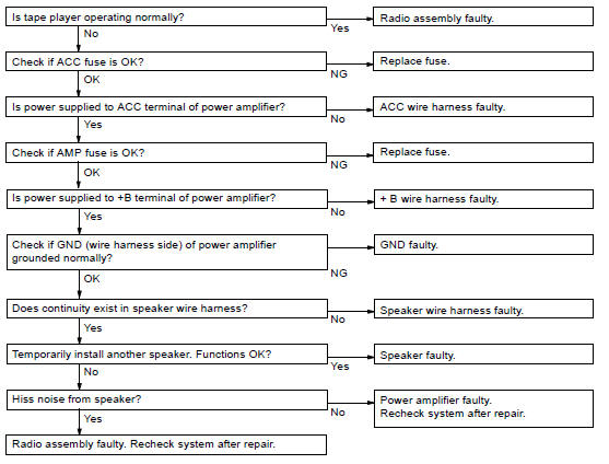
2 Radio DISPLAY INDICATES WHEN POWER SWITCH TURNED TO "ON", BUT NO SOUND (INCLUDING "NOISE") IS PRODUCED
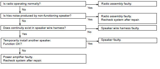
3 Radio NOISE PRESENT, BUT AM-FM NOT OPERATING
5 Radio ANY AM OR FM DOES NOR WORK FEW PRESET TUNING BANDS
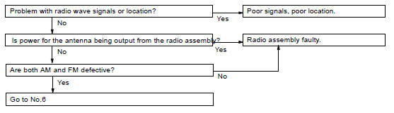
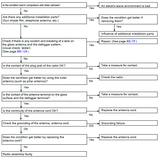
6 Radio POOR RECEPTION
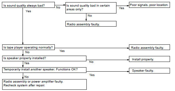
7 Radio SOUND QUALITY POOR
8 Radio PRESET MEMORY DISAPPEARS
9 Tape Player CASSETTE TAPE CANNOT BE INSERTED
10 Tape Player CASSETTE TAPE INSERTED, BUT NO POWER
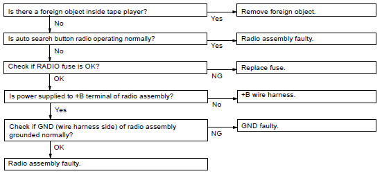
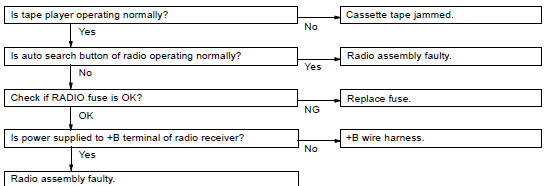
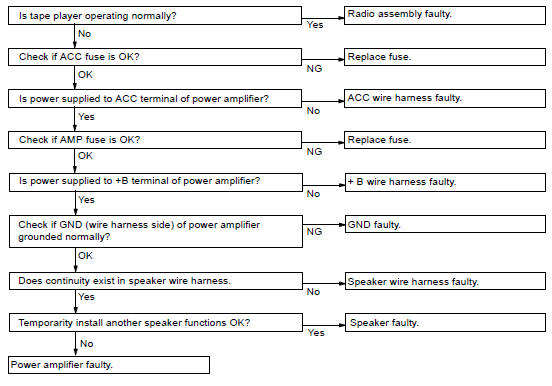
11 Tape Player POWER COMING IN, BUT TAPE PLAYER NOT OPERATING
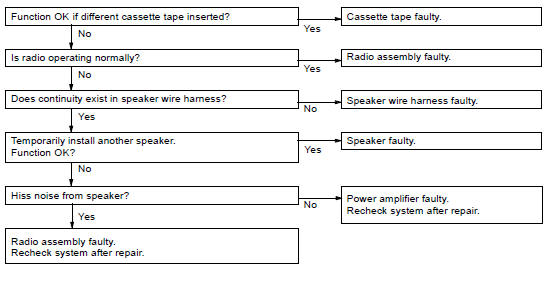
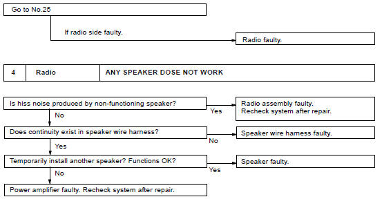
12 Tape Player ANY SPEAKER DOES NOT WORK
13 Tape Player SOUND QUALITY POOR (VOLUME FAINT)
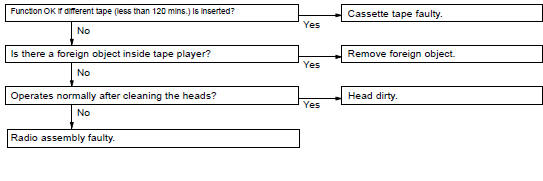
14 Tape Player TAPE JAMMED MALFUNCTION WITH TAPE SPEED OR AUTO-REVERSE
15 Tape Player CASSETTE TAPE WILL NOT BE EJECTED
16 CD Player CD CANNOT BE INSERTED
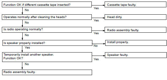
17 CD Player CD INSERTED, BUT NO POWER
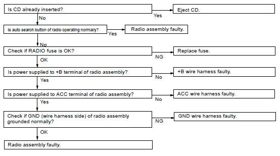
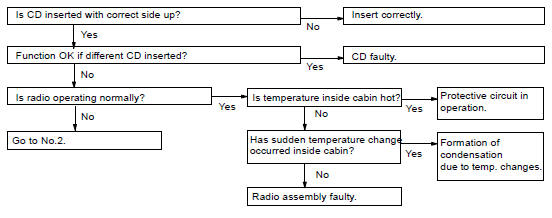
18 CD Player POWER COMING IN, BUT CD PLAYER NOT OPERATING
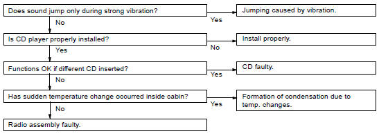
19 CD Player SOUND JUMPS
20 CD Player SOUND QUALITY POOR (VOLUME FAINT)
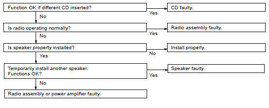
21 CD Player ANY SPEAKER DOES NOT WORK
22 CD Player CD WILL NOT BE EJECTED
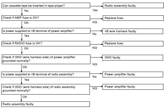
23 Power Amplifier NO POWER COMING IN
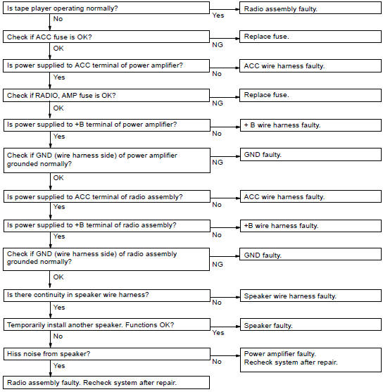
24 Power Amplifier POWER COMIMG IN, BUT WOOFER (POWER) AMPLIFIER NOT OPERATING
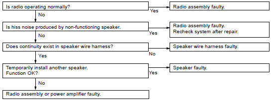
25 Power Amplifier ANY SPEAKER DOES NOT WORK
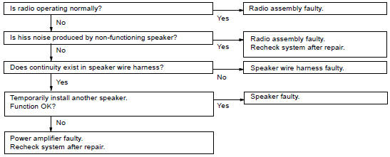
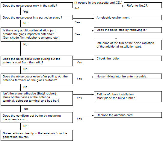
26 Noise NOISE OCCURS
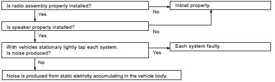
27 Noise NOISE PRODUCED BY VIBRATION OR SHOCK WHILE DRIVING
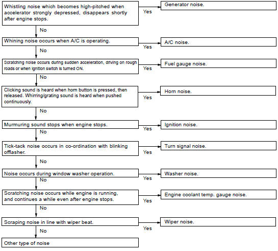
28 Noise NOISE PRODUCED WHEN ENGINE STARTS
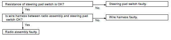
29 Steering Pad Switch A AUDIO SYSTEM CANNOT BE OPERATED WITH STEERING PAD SWITCH
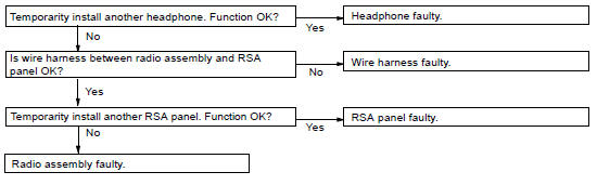
30 Rear Seat Audio QUALITY OF SOUND FROM HEADPHONE TERMINAL IS POOR OR NO SOUND CAN BE HEARD
Description
Inspection
Troubleshooting
Toyota Land Cruiser Service Manual
Categories
