 Toyota Land Cruiser Service ManualSteering » Tilt steering column
Reassembly
Reassembly
NOTICE: When using a vise, do not overtighten it.
1. COAT PARTS INDICATED BY ARROWS WITH MOLYBDENUM DISULFIDE LITHIUM BASE GREASE ( SR-12 )
2. INSTALL BUSHING
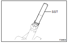
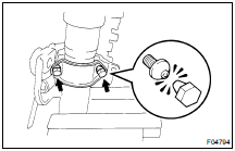
(a) Coat a new bushing with molybdenum disulfide lithium base grease.
(b) Using SST and a hammer, tap in the bushing.
SST 09612-2201 1
3. INSTALL TILT STEERING PAWL
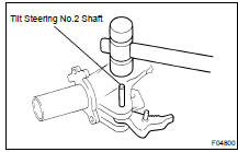
(a) Install a new pin to the pawl.
(b) Install the pawl to the column upper tube.
(c) Using a plastic hammer, tap in a new tilt steering No. 2 shaft.
NOTICE: Tap the shaft completely into the steering column upper tube.
4. INSTALL TURN SIGNAL BRACKET
Install the turn signal bracket with the 2 bolts.
5. INSTALL MAIN SHAFT ASSEMBLY
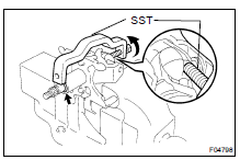
(a) Install the bearing thrust collar and compression spring to the shaft.
(b) Install the shaft assembly to the column upper tube.
(c) Using SST, compress the compression spring.
SST 09950-4001 1 (09958-04011)
NOTICE: Do not bend the universal joint of the shaft more than 20.
(d) Using a snap ring expander, install a new snap ring to the shaft.
6. INSTALL TILT LEVER RETAINER
7. INSTALL COLUMN UPPER TUBE WITH MAIN SHAFT ASSEMBLY
(a) Install the column upper tube with the main shaft to the column tube.
(b) Using a hexagon wrench, torque the 2 tilt steering bolts.
Torque: 20 N·m (210 kgf·cm, 15 ft·lbf)
(c) Check that the upper tube turns smoothly.
8. INSTALL TILT LEVER LINK
9. INSTALL TILT LEVER
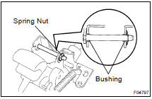
(a) Install the 2 bushings and tilt lever to the column upper tube, as shown in the illustration.
(b) Install a new spring nut to the lever.
10. INSTALL 4 TENSION SPRINGS
HINT: Install the springs with the tilt function at maximum tilt up.
11. INSTALL 2 ENERGY ABSORBING PLATES
(a) Install the 2 new energy absorbing guides and 2 new absorbing plates.
(b) Install the 2 new energy absorbing clips.
12. INSTALL COLUMN TUBE SUPPORT
Install the tube attachment with the bolt to the column tube support.
Torque: 15 N·m (150 kgf·cm, 11 ft·lbf)
13. INSTALL COLUMN UPPER BRACKET AND COLUMN UPPER CLAMP
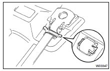
(a) Install the column upper bracket and column upper clamp with 2 new tapered-head bolts.
(b) Tighten the 2 new tapered-head bolts until the bolt heads break off.
14. INSTALL TRANSPONDER KEY AMPLIFIER ASSEMBLY
15. INSTALL INTERMEDIATE SHAFT ASSEMBLY

(a) Install the thrust stopper and upper side No. 2 lower cover.
(b) Align the matchmarks on the intermediate shaft assembly and main shaft assembly.
(c) Install the bolt.
Torque: 34 N·m (350 kgf·cm, 25 ft·lbf)
16. INSTALL NO. 2 LOWER COVER
Install the No. 2 lower cover with the 2 nuts.
Torque: 25 N·m (260 kgf·cm, 19 ft·lbf)
Disassembly
Inspection
Installation
Reassembly
Removal
Toyota Land Cruiser Service Manual
Categories
