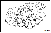
 Toyota Land Cruiser Service ManualTransfer » Transfer assembly
Reassembly
Reassembly
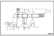
1. INSPECT SHIFT FORK NO. 2 AND CLUTCH SLEEVE CLEARANCE
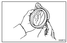
Using a feeler gauge, measure the clearance between the shift fork No. 2 and clutch sleeve.
Standard clearance: 0.10 - 0.40 mm (0.0039 - 0.0157 in.) Maximum clearance: 0.40 mm (0.0157 in.)
2. INSTALL THE BEARING RACE (FOR THE OUTPUT SHAFT)
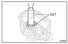
Using SST and a press, install the bearing race.
SST 09316-6001 1 (09316-00011, 09316-00031), 09950-60020 (09951-00890)
3. INSTALL THE BEARING RACE (FOR THE IDLER GEAR)
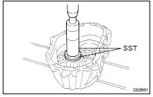
Using SST and a press, install the bearing race.
SST 09316-6001 1 (09316-00011, 09316-00031), 09950-60020 (09951-00790)
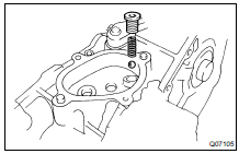
4. INSTALL OIL RECEIVER TO FRONT CASE
Install the oil receiver and bolt.
Torque: 12 N·m (120 kgf·cm, 9 ft·lbf)
5. INSTALL SHIFT OUTER LEVER AND INNER LEVER
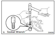
(a) Install the shift inner lever, washer and outer lever to the front case.
(b) Using a pin punch, hammer and socket wrench, tap in the lever lock pin.
(c) Install the washer and nut to the shift outer lever.
Torque: 12 N·m (120 kgf·cm, 9 ft·lbf)
6. ASSEMBLE SHIFT FORK NO. 1 AND SHIFT FORK NO. 1 SHAFT
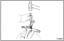
(a) Assemble the shift fork No. 1 and shift fork No. 1 shaft.
(b) Using a pin punch and hammer, drive in the slotted spring pin.
7. INSTALL IDLER GEAR ASSEMBLY WITH CENTER DIFFERENTIAL ASSEMBLY, SHIFT FORK NO. 1 AND SHIFT FORK NO. 1 SHAFT TO FRONT CASE
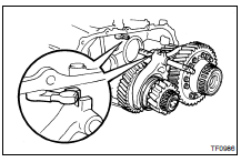
NOTICE: Set the shift inner lever into the fork head part of the shift fork No. 1 securely.
8. INSTALL INPUT SHAFT ASSEMBLY
9. INSTALL 2 BEARING RACES TO REAR CASE
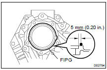
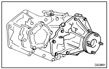
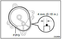
10. ASSEMBLY FRONT CASE AND REAR CASE
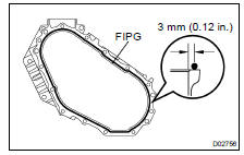
(a) Apply FIPG to the front case.
FIPG: Part No. 08826-00090, THREE BOND 1281 or equivalent
(b) Assemble the front case and rear case.
(c) Apply liquid sealer to the "A" bolt threads.
Sealant: Part No. 08833-00080, THREE BOND 1344, LOCTITE 242 or equivalent
(d) Install the 8 bolts.
Torque: 37 N·m (380 kgf·cm, 27 ft·lbf)
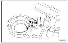
11. ASSEMBLE FRONT CASE AND REAR CASE
Using a snap ring expander, install the snap ring to the rear case.
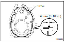
12. INSTALL CASE COVER
(a) Apply FIPG to the rear case.
FIPG: Part No. 08826-00090, THREE BOND 1281 or equivalent
(b) Install the case cover.
(c) Apply liquid sealer to the bolt threads.
Sealant: Part No. 08833-00080, THREE BOND 1344, LOCTITE 242 or equivalent
(d) Install the 5 bolts.
Torque: 37 N·m (380 kgf·cm, 27 ft·lbf)
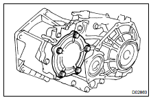
13. INSTALL OIL STRAINER TO REAR CASE
Install the oil strainer and 2 bolts.
Torque: 4.9 N·m (50 kgf·cm, 43 in.·lbf)
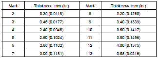
14. SELECT ADJUSTING SHIM FOR IDLER GEAR REAR TAPER ROLLER BEARING
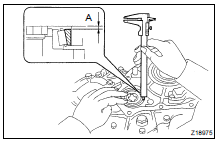
(a) Using vernier calipers, measure dimension "A".
(b) Lightly hole down the bearing outer race in the thrust direction to eliminate any looseness before making the measurement.
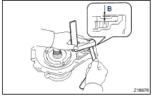
(c) Using a steel straight edge and feeler gauge, measure the clearance of dimension "B".
(d) Calculate the required thickness of the adjusting shim.
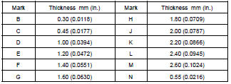
Thickness: Dimension "A" + Dimension "B" + [0.022 - 0.049 mm, (0.0009 - 0.0019 in.)] (e) From the following table, select a shim so that its thickness is within the range of the calculation
15. SELECT ADJUSTING SHIM FOR OUTPUT SHAFT TAPER ROLLER BEARING
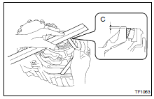
(a) Using a steel straight edge and feeler gauge, measure the clearance of dimension "C".
(b) Lightly hold down the bearing outer race in the thrust direction to eliminate any looseness before making the measurement.
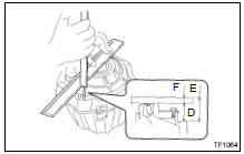
(c) Using a steel straight edge and vernier calipers with depth gauge, measure dimension "D".
(d) Dimension "D" is the straight edge thickness (Dimension "F") subtracted from dimension "E" in the illustration to the left.
Dimension "D": Dimension "E" - Dimension "F"
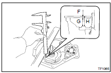
(e) Using a steel straight edge and vernier calipers with depth gauge, measure dimension "G".
(f) Dimension "G" is the straight edge thickness (Dimension "F") subtracted from Dimension "H".
Dimension "G": Dimension "H" - Dimension "F" (g) Calculate the required thickness of the adjusting shim.
Thickness: Dimension "G" - (Dimension "D" - Dimension
"C") + [0.014 ~ 0.039 mm, (0.0006 ~ 0.0015
in.)]
(h) From the following table, select a shim so that its thickness
is within the range of the calculation.
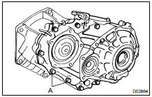
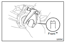
16. INSTALL REAR EXTENSION HOUSING
(a) Apply FIPG to the rear extension housing.
FIPG: Part No. 08826-00090, THREE BOND 1281 or equivalent
(b) Install the rear extension housing and 9 bolts.
Torque: 37 N·m (380 kgf·cm, 27 ft·lbf)
17. ASSEMBLE SHIFT FORK NO. 2 SHAFT AND SHIFT FORK NO. 2
(a) Install the shift fork No. 2 to the shift fork No. 2 shaft.
(b) Install the 3 snap rings to the shift fork No. 2 shaft.
18. INSTALL CLUTCH SLEEVE WITH SHIFT FORK NO. 2 SHAFT AND SHIFT FORK NO. 2
HINT: Make sure to install the clutch sleeve in the correct direction.
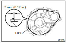
19. INSTALL FRONT EXTENSION HOUSING
(a) Apply FIPG to the front extension housing.
FIPG: Part No. 08826-00090, THREE BOND 1281 or equivalent
(b) Install the front extension housing and 6 bolts.
Torque: 37 N·m (380 kgf·cm, 27 ft·lbf)
HINT: Set the clutch sleeve in differential lock condition.
20. INSTALL TRANSFER INDICATOR SWITCH
Install the 3 transfer indicator switches with 3 new gaskets.
Torque: 37 N·m (380 kgf·cm, 27 ft·lbf)
21. INSTALL BALL, SPRING AND SCREW
(a) Install the ball and spring.
(b) Apply liquid sealer to the screw plug threads.
Sealant: Part No. 08833-00080, THREE BOND 1344, LOCTITE 242 or equivalent
(c) Using a torx socket wrench (T40), install the screw plug.
Torque: 19 N·m (190 kgf·cm, 14 ft·lbf)
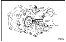
22. INSTALL OUTPUT GEAR TO FRONT CASE
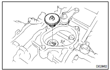
HINT: Apply gear oil to the output gear.
NOTICE: Do not turn the output gear.
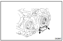
23. INSTALL MOTOR ACTUATOR
(a) Apply FIPG to the motor actuator.
FIPG: Part No. 08826-00090, THREE BOND 1281 or equivalent
HINT: Set the motor actuator in differential lock condition.
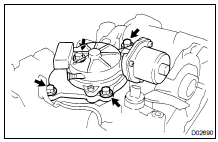
(b) Install the motor actuator and 4 bolts.
Torque: 18 N·m (185 kgf·cm, 13 ft·lbf)
24. INSTALL SPEED SENSOR DRIVE GEAR
Install the driven gear and bolt.
Torque: 11 N·m (115 kgf·cm, 8 ft·lbf)
25. INSTALL BREATHER HOSE
Disassembly
Reassembly
Toyota Land Cruiser Service Manual
Categories
