 Toyota Land Cruiser Service ManualSFI » SRS airbag
Operation
Operation
1. STEERING WHEEL PAD (with AIRBAG)
The inflater and bag of the SRS are stored in the steering wheel pad and cannot be disassembled. The inflater contains a squib, igniter charge, gas generator, etc., and inflates the bag when instructed by the airbag sensor assembly.
2. SPIRAL CABLE (in COMBINATION SWITCH)
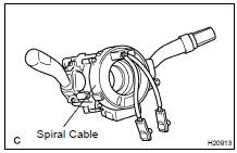
A spiral cable is used as an electrical joint from the vehicle body side to the steering wheel.
3. FRONT PASSENGER AIRBAG ASSEMBLY
The inflater and bag of the SRS are stored in the front passenger airbag assembly and cannot be disassembled. The inflater contains a squib, igniter charge, gas generator, etc., and inflates the bag when instructed by the airbag sensor assembly.
4. SIDE AIRBAG ASSEMBLY
The inflater and bag of the SRS side airbag are stored in the side airbag assembly and cannot be disassembled. The inflater contains a squib, igniter charge, gas generator, etc., and inflates the bag when instructed by the side airbag sensor assembly.
5. CURTAIN SHIELD AIRBAG ASSEMBLY
The inflater and bag of the SRS are stored in the curtain shield airbag assembly and cannot be disassembled. The inflater contains a squib, igniter charge, gas generator, etc., and inflates the bag when instructed by the side airbag sensor assembly.
6. SEAT BELT PRETENSIONER
The seat belt pretensioner system is a component of the front seat outer belt. The seat belt pretensioner cannot be disassembled.
7. SRS WARNING LIGHT
The SRS warning light is located on the combination meter. It goes on to alert the driver of trouble in the system when a malfunction is detected in the airbag sensor assembly self-diagnosis.
In normal operating conditions when the ignition switch is turned to the ON position, the light comes on for about 3 seconds and then goes off.
8. AIRBAG SENSOR ASSEMBLY
The airbag sensor assembly is mounted on the floor inside the front console box. The airbag sensor assembly consists of an airbag sensor, safing sensor, diagnosis circuit, ignition control, drive circuit, etc. It receives signals from the airbag sensor, front airbag sensor, side and curtain shield airbag sensor assembly, curtain shield airbag sensor assembly and judges whether the SRS must be activated or not. The airbag sensor assembly cannot be disassembled.
9. FRONT AIRBAG SENSOR
The front airbag sensor is mounted on each of the radiator side supports. The front airbag sensor consists of a frontal deceleration sensor, diagnosis circuit, etc. These send signals to the airbag sensor assembly. The front airbag sensor cannot be disassembled.
10. SIDE AND CURTAIN SHIELD AIRBAG SENSOR ASSEMBLY
The side and curtain shield airbag sensor assembly is mounted in the LH and RH center pillars. The side and curtain shield airbag sensor assembly consist of a lateral deceleration sensor, safing sensor, diagnosis circuit, etc. These send signals to the airbag sensor assembly to judge whether the SRS side airbag and curtain shield airbag must be activated or not. The side and curtain shield airbag sensor assembly cannot be disassembled.
11. CURTAIN SHIELD AIRBAG SENSOR ASSEMBLY
The curtain shield airbag sensor assembly is mounted in the LH and RH rear pillars. The curtain shield airbag sensor assembly consists of a lateral deceleration sensor, safing sensor, diagnosis circuit, etc. These sensors send signals to the airbag sensor assembly to judge whether the SRS curtain shield airbag must be activated or not. The curtain shield airbag sensor assembly cannot be disassembled.
12. SEAT POSITION SENSOR ASSEMBLY
The seat position sensor assembly is mounted on the seat rail of the driver's seat. The sensor unit consists of a magnet sensor, diagnosis circuit, etc. It judges the seat sliding position and sends the signal to the airbag sensor assembly. The seat position sensor assembly cannot be disassembled.
13. SRS CONNECTORS
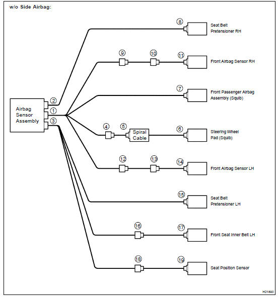
HINT: SRS connectors are located as shown in the following illustration.
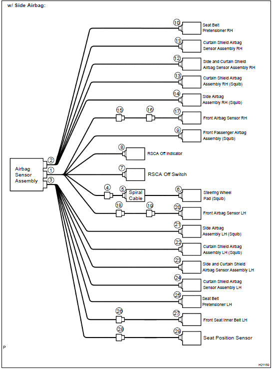
(a) All connectors in the SRS are colored in yellow to distinguish them from other connectors. Connectors having special functions and specifically designed for the SRS are used in the locations shown on the previous page to ensure high reliability. These connectors use durable gold-plated terminals.
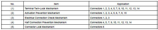
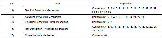
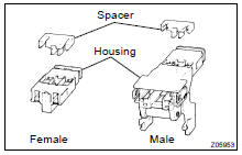
- Terminal Twin-Lock Mechanism Each connector has a two-piece component consisting of a housing and a spacer. This design allows the terminal to be locked securely by two locking devices (the retainer and the lance) to prevent terminals from coming out.
- Activation Prevention Mechanism Each connector contains a short spring plate. When the connector is disconnected, the short spring plate automatically connects positive (+) terminal and negative (-) terminal of the squib.
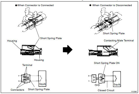
HINT: The type of connector is shown in the diagram on the previous page.
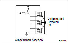
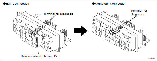
- Electrical Connection Check Mechanism This mechanism electrically checks that connectors are connected correctly and completely. The electrical connection check mechanism is designed so that the disconnection detection pin is connected with the diagnosis terminals when the connector housing lock is locked.
HINT:
- The illustration shows connectors "1", "2" and "3" in step 13.
- Connectors 2 and 3 also have similar mechanism.
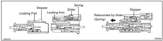
- Half connection prevention mechanism: If the connector is not completely connected, the connector is disconnected due to the spring operation to the extent that no continuity exists.

- Connector lock mechanism: Locking the connector lock button securely connects the connector.
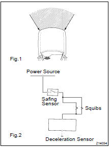
(b) When the vehicle is involved in a frontal collision in the hatched area (Fig. 1) and the shock is larger than the predetermined level, the SRS is activated automatically. A safing sensor is designed to go on at a smaller deceleration rate than the airbag sensor. As illustrated in Fig. 2, ignition is caused when current flows to the squib, which happens when a safing sensor and the deceleration sensor go on simultaneously. When a deceleration force acts on the sensors, 2 squibs in the driver airbag and front passenger airbag ignite and generate gas. The gas discharging into the driver airbag and front passenger airbag rapidly increases the pressure inside the bags, breaking open the steering wheel pad and instrument panel.
Bag inflation then ends, and the bags deflate as the gas is discharged through discharge holes at the bag's rear or side.
14. DISCONNECTION OF CONNECTORS FOR FRONT AIRBAG SENSOR, SIDE AND CURTAIN SHIELD AIRBAG SENSOR AND CURTAIN SHIELD AIRBAG SENSOR
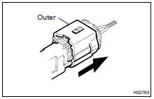
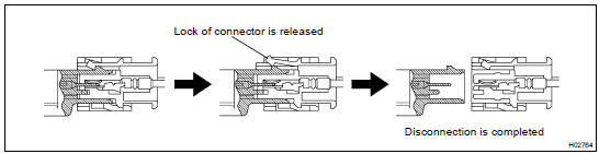
(a) While holding both flank sides of the outer, slide the outer in the direction shown by an arrow.
(b) Lock of the connectors is released, and then disconnect the connectors.
HINT: Be sure to hold both flank sides of the outer. If holding the top and bottom sides, it will obstruct disconnection.
15. CONNECTION OF CONNECTORS FOR FRONT AIRBAG SENSOR, SIDE AND CURTAIN SHIELD AIRBAG SENSOR AND CURTAIN SHIELD AIRBAG SENSOR
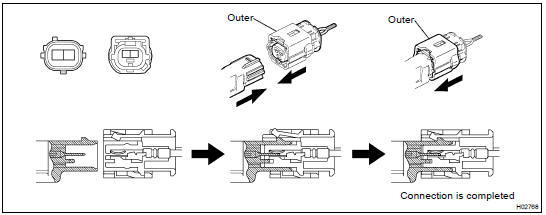
(a) Align the male connector (of the side of sensor) and female connector in the same direction as shown in the illustration and fit them in without rubbing.
(b) As they are fitted in, the outer slides rearward. Press it until the outer returns to its original position again.
If fitting stops half way, connectors will separate.
(c) Be sure to insert until they are locked. After fitting in, pull them slightly to check that they are locked. (When locked, make sure that the outer returns to its original position and sound to be fit in can be heard.)
HINT:
- Do not fit in while holding the outer.
- When fitting in, the outer slides. Do not touch it.
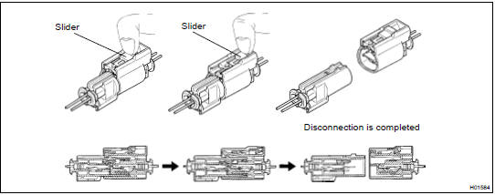
16. DISCONNECTION OF SIDE AIRBAG CONNECTOR
(a) Place a finger on the slider.
(b) Slide the slider to release lock.
(c) Disconnect the connector.
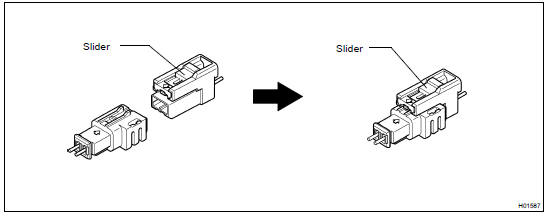
17. CONNECTION OF SIDE AIRBAG CONNECTOR
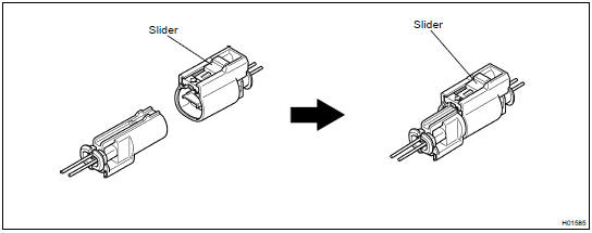
(a) Align a lock part of male connector and a slider of female connector in the same direction as shown in the illustration, fit them in without rubbing.
(b) Be sure to insert until they are locked. After fitting in pull them slightly to check that they are locked. (When locked, make sure that the outer returns to its original position and sound to be fit in can be heard.)
HINT:
- As the slider slides, do not touch it.
- Be careful not to deform the release board. If the release board is deformed, replace it with a new one.
18. DISCONNECTION OF CONNECTORS FOR CURTAIN SHIELD AIRBAG ASSEMBLY AND FRONT PASSENGER AIRBAG ASSEMBLY
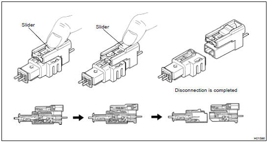
(a) Place a finger on the slider.
(b) Slide the slider to release lock.
(c) Disconnect the connector.
19. CONNECTION OF CONNECTORS FOR CURTAIN SHIELD AIRBAG ASSEMBLY AND FRONT PASSENGER AIRBAG ASSEMBLY
(a) Align a lock part of male connector and a slider of female connector in the same direction as shown in the illustration, fit them in without rubbing.
(b) Be sure to insert until they are locked. After fitting in pull them slightly to check that they are locked. (When locked, make sure that the outer returns to its original position and sound to be fit in can be heard.)
HINT:
- As the slider slides, do not touch it.
- Be careful not to deform the release board. If the release board is deformed, replace it with a new one.
Operation
Precaution
Toyota Land Cruiser Service Manual
Categories
