 Toyota Land Cruiser Service ManualEngine Mechanical » Engine unit
Installation
Installation
1. INSTALL DRIVE PLATE
HINT:
- The mounting bolts are tightened in 2 steps (steps (c) and (e)).
- If any one of the mounting bolts is broken or deformed, replace it.
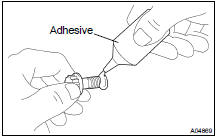
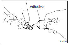
(a) Apply adhesive to 2 or 3 threads of the mounting bolt end.
Adhesive: Part No. 08833-00070, THREE BOND 1324 or equivalent
(b) Install the front spacer, the drive plate and the rear spacer on the crankshaft.
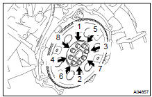
(c) Hold the crankshaft pulley bolt with a wrench, and install and evenly tighten the 8 mounting bolts, a little at a time for several times as in the sequence shown.
Torque: 49 N·m (500 kgf·cm, 36 ft·lbf)
If any one of the mounting bolts does not meet the torque specification, replace the mounting bolt.
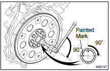
(d) Mark the mounting bolt with paint.
(e) Retighten the mounting bolts by 90 in the numerical order shown.
(f) Check that the painted mark is now at a 90 angle to (e).
2. INSTALL TRANSMISSION TO ENGINE
(a) Check the torque converter clutch installation.
( AT-33 )
(b) Attach the transmission to the engine.
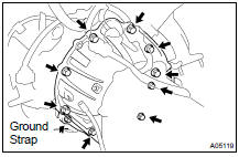
(c) Install the ground strap and 10 bolts.
Torque:
37 N·m (380 kgf·cm, 27 ft·lbf) for 14 mm head
72 N·m (730 kgf·cm, 53 ft·lbf) for 17 mm head
3. INSTALL TORQUE CONVERTER CLUTCH BOLTS
(a) Apply adhesive to 2 or 3 threads from the bolt end.
Adhesive: Part No. 08833-00070, THREE BOND 1324 or equivalent
(b) Hold the crankshaft pulley bolt with a wrench, and install the 6 bolts evenly.
Torque: 48 N·m (490 kgf·cm, 35 ft·lbf)
HINT: First install the black colored bolt, install the other bolts.
(c) Install the flywheel housing under cover with the bolt.
Torque: 18 N·m (185 kgf·cm, 13 ft·lbf)
4. INSTALL OIL COOLER PIPE FOR TRANSMISSION
5. CONNECT ENGINE WIRE TO TRANSMISSION
(a) Connect the 5 connectors.
(b) Connect the 2 wire clamps
6. INSTALL ENGINE AND TRANSMISSION ASSEMBLY IN VEHICLE
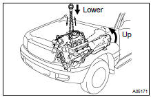
(a) Attach the engine chain hoist to the engine hangers.
(b) Slowly lower the engine and the transmission assembly into the engine compartment.
(c) Attach the engine mounting brackets to the frame brackets.
(d) Keep the engine level with a jack.
(e) Install the frame crossmember with the 8 bolts and the 4 nuts.
Torque:
50 N·m (510 kgf·cm, 37 ft·lbf) for bolts
74 N·m (750 kgf·cm, 55 ft·lbf) for nuts
(f) Install the transfer case protector with the 3 bolts.
(g) Install the 2 nuts and the 4 bolts holding the engine mounting brackets to the frame brackets.
Torque: 30 N·m (310 kgf·cm, 22 ft·lbf)
(h) Remove the engine chain hoist.
7. INSTALL PS PUMP
Install the PS pump with the 3 bolts.
Torque: 62 N·m (632 kgf·cm, 46 ft·lbf)
8. INSTALL A/C COMPRESSOR
(a) Install the A/C compressor with the 3 bolts.
Torque: 49 N·m (500 kgf·cm, 36 ft·lbf)
(b) Connect the A/C compressor connector.
9. INSTALL STABILIZER BAR ( SA-82 )
10. INSTALL PROPELLER SHAFT ( PR-7 )
11. INSTALL FRONT EXHAUST PIPES
12. INSTALL SHIFT LEVER ASSEMBLY AND TRANSFER SHIFT LEVER ASSEMBLY
(a) Install the transfer shift lever.
- Install a new gasket and the shift lever with the 4 bolts.
- Connect the transfer shift lever rod to the shift lever with the bushing, the wave washer, the plate washer and the clip.
(b) Install the transfer shift lever boot with the 4 bolts.
(c) Install the shift lever assembly.
- Connect the transmission control rod to the shift lever assembly with the nut.
Torque: 13 N·m (130 kgf·cm, 9 ft·lbf)
- Install the shift lever assembly with the 6 bolts.
Torque: 8.3 N·m (86 kgf·cm, 73 in.·lbf)
- Connect the connector.
(d) Install the console upper cover.
(e) Install the transfer shift lever knob.
13. CONNECT HOSES, WIRES, CONNECTORS, CLAMPS, GROMMET AND CABLES
(a) Connect the 2 PS air hoses to the hose clamp on the No.3 RH timing belt cover.
(b) Connect the generator wire.
(c) Connect the generator connector.
(d) Connect the hose clamp for the PS air hose.
(e) Connect the PS air hose to upper intake manifold.
(f) Connect the 2 heater hoses.
(g) Connect the engine wire clamp to the bracket on the cowl panel.
(h) Connect the engine wire grommet to the cowl panel.
(i) Connect the ground strap connector.
(j) Connect the fuel main hose and the clamps.
(k) Connect the fuel return hose and the clamp.
(l) Connect the air inlet hose to the charcoal canister.
(m) Connect the EVAP hose to the charcoal canister.
(n) Connect the engine wire to the clamp on the right fender apron.
(o) Connect the clamp on battery negative (-) cable to the relay box.
(p) Connect the battery negative (-) cable to the right fender apron.
(q) Connect the battery positive (+) terminal cable.
14. CONNECT ENGINE WIRE TO CABIN
(a) Connect the 3 wire harness connectors.
(b) Install the ECM with the 3 screws.
(c) Connect the 3 connectors to the ECM.
(d) Install the glove compartment door.
(e) Install the lower No.2 panel.
15. INSTALL FAN PULLEY, FAN, FLUID COUPLING AND GENERATOR DRIVE BELT
(a) Temporarily install the fan pulley, the fan and the fluid coupling assembly with the 4 nuts.
(b) Install the generator drive belt. ( CH-16 ) (c) Tighten the 4 nuts holding the fluid coupling to the fan bracket.
16. INSTALL RADIATOR AND FAN SHROUD
(a) Place the fan shroud in the installation position.
(b) Install the radiator with the 2 support collars, the 2 nuts and the 2 bolts.
(c) Connect the 2 A/T oil cooler hoses to the radiator.
(d) Install the lower radiator hose.
(e) Attach the lower side of the fan shroud to the brackets of the radiator, and install the fan shroud with the 2 bolts.
(f) Install the 2 brackets on the wire to the radiator with the 2 bolts.
(g) Install the 2 clamps on the A/C discharge tube to the brackets on the wire with the 2 nuts.
(h) Connect the upper radiator hose to the front water bypass joint.
17. INSTALL RADIATOR RESERVOIR
(a) Install the grommet to the reservoir.
(b) Attach the lower side of the reservoir to the fan shroud.
(c) Install the reservoir with the 2 bolts.
(d) Connect the reservoir hose to the radiator.
(e) Install the clamp on the wire to the reservoir.
18. INSTALL AIR CLEANER CAP AND INTAKE AIR CONNECTOR PIPE ASSEMBLY
19. INSTALL BATTERY
20. FILL WITH ENGINE COOLANT ( CO-2 )
21. FILL WITH ENGINE OIL ( LU-2 )
22. START ENGINE AND CHECK FOR LEAKS
23. INSTALL V-BANK COVER
24. INSTALL ENGINE UNDER COVERS
25. INSTALL HOOD
26. PERFORM ROAD TEST
Check for abnormal noise, shock, slippage, and make sure the shift points is correct and operation is smooth.
27. RECHECK ENGINE COOLANT AND OIL LEVELS
Components
Installation
Removal
Toyota Land Cruiser Service Manual
Categories
