 Toyota Land Cruiser Service ManualBody Electrical » Power door lock control system
Inspection
Inspection
1. Master switch: INSPECT DRIVER'S DOOR LOCK CONTROL SWITCH CONTINUITY
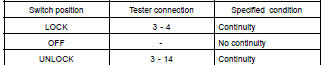
If continuity is not as specified, replace the switch.
2. INSPECT PASSENGER'S DOOR LOCK CONTROL SWITCH CONTINUITY
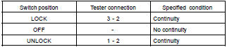
If continuity is not as specified, replace the switch.
3. Front door: INSPECT DOOR UNLOCK DETECTION SWITCH CONTINUITY
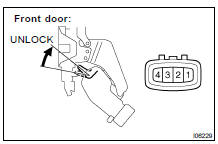
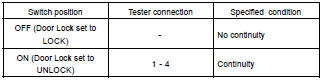
If continuity is not as specified, replace the switch.
4. Rear door: INSPECT DOOR UNLOCK DETECTION SWITCH CONTINUITY
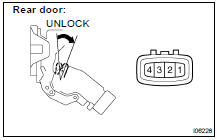
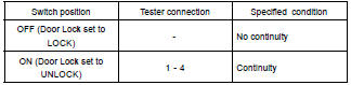
If continuity is not as specified, replace the switch.
5. Back door: INSPECT DOOR UNLOCK DETECTION SWITCH CONTINUITY
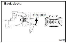
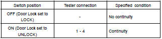
If continuity is not as specified, replace the switch
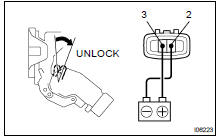
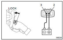
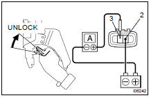
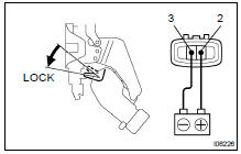
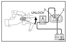
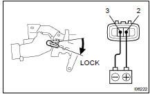
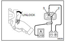
6. Front door: INSPECT DOOR LOCK MOTOR OPERATION
(a) Connect the positive (+) lead from the battery to terminal 3 and the negative (-) lead to terminal 2, and check that the door lock link moves to UNLOCK position.
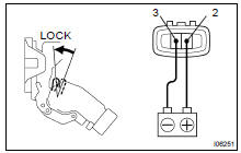
(b) Reverse the polarity and check that the door lock link moves to LOCK position.
If operation is not as specified, replace the door lock assembly.
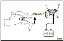
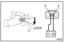
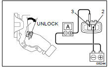
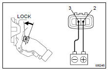
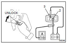
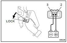
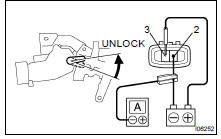
7. Rear door: INSPECT DOOR LOCK MOTOR OPERATION
(a) Connect the positive (+) lead from the battery to terminal 3 and the negative (-) lead to terminal 2, and check that the door lock link moves to UNLOCK position
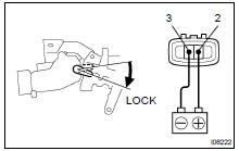
(b) Reverse the polarity and check that the door lock link moves to LOCK position.
If operation is not as specified, replace the door lock assembly.
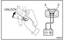
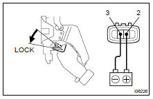
8. Back door: INSPECT DOOR LOCK MOTOR OPERATION
(a) Connect the positive (+) lead from the battery to terminal 3 and the negative (-) lead to terminal 2, and check that the door lock link moves to UNLOCK position
(b) Reverse the polarity and check that the door lock link moves to LOCK position.
If operation is not as specified, replace the door lock assembly.
9. Front door: INSPECT PTC THERMISTOR OPERATION (Using an ammeter)
(a) Connect the negative (-) lead from the battery to terminal 2.
(b) Connect the positive (+) lead from the ammeter to terminal 3 and the negative (-) lead to battery negative (-) terminal, and check that the current changes from approximately 3.2 A to less than 0.5 A within 20 to 70 seconds.
(c) Disconnect the leads from terminals.
(d) Approximately 60 seconds later, connect the positive (+) lead from the battery to terminal 2 and the negative (-) lead to terminal 3, and check that the door lock moves to the LOCK position.
If operation is not as specified, replace the door lock assembly.
10. Rear door: INSPECT PTC THERMISTOR OPERATION (Using an ammeter)
(a) Connect the negative (-) lead from the battery to terminal 2.
(b) Connect the positive (+) lead from the ammeter to terminal 3 and the negative (-) lead to battery negative (-) terminal, and check that the current changes from approximately 3.2 A to less than 0.5 A within 20 to 70 seconds.
(c) Disconnect the leads from terminals.
(d) Approximately 60 seconds later, connect the positive (+) lead from the battery to terminal 2 and the negative (-) lead to terminal 3, and check that the door lock moves to the LOCK position.
If operation is not as specified, replace the door lock assembly.
11. Back door: INSPECT PTC THERMISTOR OPERATION (Using an ammeter)
(a) Connect the negative (-) lead from the battery to terminal 2.
(b) Connect the positive (+) lead from the ammeter to terminal 3 and the negative (-) lead to battery negative (-) terminal, and check that the current changes from approximately 3.2 A to less than 0.5 A within 20 to 70 seconds.
(c) Disconnect the leads from terminals.
(d) Approximately 60 seconds later, connect the positive (+) lead from the battery to terminal 2 and the negative (-) lead to terminal 3, and check that the door lock moves to the LOCK position.
If operation is not as specified, replace the door lock assembly.
12. Front door: INSPECT PTC THERMISTOR OPERATION (Using an ammeter with a current-measuring probe)
(a) Connect the positive (+) lead from the battery to terminal 3 and the negative (-) lead to terminal 2.
(b) Attach a current-measuring probe to either the positive (+) lead or the negative (-) lead, and check that the current changes from approximately 3.2 A to less than 0.5 A within 20 to 70 seconds.
(c) Disconnect the leads from terminals.
(d) Approximately 60 seconds later, reverse the polarity, and check that the door lock moves to the LOCK position.
If operation is not as specified, replace the door lock assembly.
13. Rear door: INSPECT PTC THERMISTOR OPERATION (Using an ammeter with a current-measuring probe)
(a) Connect the positive (+) lead from the battery to terminal 3 and the negative (-) lead to terminal 2.
(b) Attach a current-measuring probe to either the positive (+) lead or the negative (-) lead, and check that the current changes from approximately 3.2 A to less than 0.5 A within 20 to 70 seconds.
(c) Disconnect the leads from terminals.
(d) Approximately 60 seconds later, reverse the polarity, and check that the door lock moves to the LOCK position.
If operation is not as specified, replace the door lock assembly
14. Back door: INSPECT PTC THERMISTOR OPERATION (Using an ammeter with a current-measuring probe)
(a) Connect the positive (+) lead from the battery to terminal 3 and the negative (-) lead to terminal 2.
(b) Attach a current-measuring probe to either the positive (+) lead or the negative (-) lead, and check that the current changes from approximately 3.2 A to less than 0.5 A within 20 to 70 seconds.
(c) Disconnect the leads from terminals.
(d) Approximately 60 seconds later, reverse the polarity, and check that the door lock moves to the LOCK position.
If operation is not as specified, replace the door lock assembly.
Inspection
Location
Toyota Land Cruiser Service Manual
Categories
