 Toyota Land Cruiser Service ManualIntroduction
How to use the diagnostic
chart and inspection
How to use the diagnostic chart and inspection
PROCEDURE
1. CONNECTOR CONNECTION AND TERMINAL INSPECTION
- For troubleshooting, diagnostic trouble code charts or problem symptom table are provided for each circuit with detailed inspection procedures on the following pages.
- When all the component parts, wire harnesses and connectors of each circuit except the ECU are found to be normal in troubleshooting, then it is determined that the problem is in the ECU. Accordingly, if diagnosis is performed without the problem symptoms occurring, refer to Step 8 to replace the ECU. So always confirm that the problem symptoms are occurring, or proceed with inspection while using the symptom simulation method.
- The instructions "Check wire harness and connector" and "Check and replace ECU" which appear in the inspection procedure, are common and applicable to all diagnostic trouble codes. Follow the procedure outlined below whenever these instructions appear.
OPEN CIRCUIT: This could be due to a disconnected wire harness, faulty contact in the connector, and a connector terminal pulled out, etc.
HINT:
- It is rarely the case that a wire is broken in the middle of it. Most cases occur at the connector. In particular, carefully check the connectors of sensors and actuators
- Faulty contact could be due to rusting of the connector terminals, to foreign materials entering terminals or a deformation of connector terminals. Simply disconnecting and reconnecting the connectors once changes the condition of the connection and may result in a return to normal operation. Therefore, in troubleshooting, if no abnormality is found in the wire harness and connector check, but the problem disappears after the check, then the cause is considered to be in the wire harness or connectors.
SHORT CIRCUIT: This could be due to a contact between wire harness and the body ground or to a short circuit occurred inside the switch, etc.
HINT: When there is a short circuit between the wire harness and body ground, check thoroughly whether the wire harness is caught in the body or is clamped properly.
2. CONNECTOR HANDLING
When inserting tester probes into a connector, insert them from the rear of the connector. When necessary, use mini test leads.
For water resistant connectors which cannot be accessed from behind, take good care not to deform the connector terminals
3. CONTINUITY CHECK (OPEN CIRCUIT CHECK)
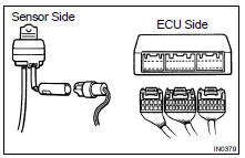
(a) Disconnect the connectors at both ECU and sensor sides.
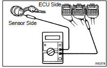
(b) Measure the resistance between the applicable terminals of the connectors.
Resistance: 1 W or less
HINT: Measure the resistance while lightly shaking the wire harness vertically and horizontally.
4. RESISTANCE CHECK (SHORT CIRCUIT CHECK)
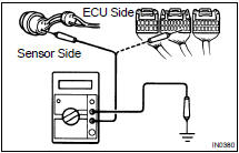
(a) Disconnect the connectors on both ends.
(b) Measure the resistance between the applicable terminals of the connectors and body ground. Be sure to carry out this check on the connectors on both ends.
Resistance: 1 MW or higher
HINT: Measure the resistance while lightly shaking the wire harness vertically and horizontally.
5. VISUAL CHECK AND CONTACT PRESSURE CHECK
(a) Disconnect the connectors at both ends.
(b) Check for rust or foreign material, etc. in the terminals of the connectors.
(c) Check crimped portions for looseness or damage and check that the terminals are secured in lock portion.
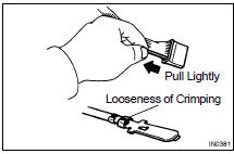
HINT: The terminals should not come out when pulled lightly from the back.
(d) Prepare a test male terminal and insert it in the female terminal, then pull it out.
NOTICE: When testing a gold-plated female terminal, always use a gold-plated male terminal.
HINT: When the test terminal is pulled out more easily than others, there may be poor contact in that section.
6. CHECK OPEN CIRCUIT
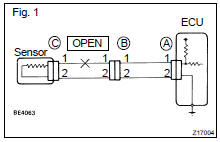
For the open circuit in the wire harness in Fig. 1, perform "(a) Continuity Check" or "(b) Voltage Check" to locate the section.
(a) Check the continuity.
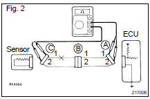
- Disconnect connectors "A" and "C" and measure
the resistance between them.
In the case of Fig. 2, Between terminal 1 of connector "A" and terminal 1 of connector "C" " No continuity (open) Between terminal 2 of connector "A" and terminal 2 of connector "C" " Continuity Therefore, it is found out that there is an open circuit between terminal 1 of connector "A" and terminal 1 of connector "C".
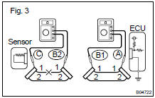
- Disconnect connector "B" and measure the resistance
between the connectors.
In the case of Fig. 3, Between terminal 1 of connector "A" and terminal 1 of connector "B1" " Continuity Between terminal 1 of connector "B2" and terminal 1 of connector "C" " No continuity (open) Therefore, it is found out that there is an open circuit between terminal 1 of connector "B2" and terminal 1 of connector "C".
(b) Check the voltage.
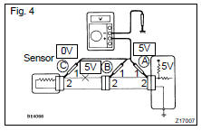
In a circuit in which voltage is applied (to the ECU connector terminal), an open circuit can be checked for by conducting a voltage check.
As shown in Fig. 4, with each connector still connected, measure the voltage between body ground and terminal 1 of connector "A" at the ECU 5V output terminal, terminal 1 of connector "B", and terminal 1 of connector "C", in that order.
If the results are:
5V: Between Terminal 1 of connector "A" and Body Ground
5V: Between Terminal 1 of connector "B" and Body Ground
0V: Between Terminal 1 of connector "C" and Body Ground
Then it is found out that there is an open circuit in the wire harness between terminal 1 of "B" and terminal 1 of "C".
7. CHECK SHORT CIRCUIT
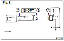
If the wire harness is ground shorted as in Fig. 5, locate the section by conducting a "continuity check with ground".
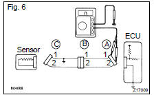
Check the continuity with ground.
- Disconnect connectors "A" and "C" and measure
the resistance between terminal 1 and 2 of connector
"A" and body ground.
In the case of Fig. 6 Between terminal 1 of connector "A" and body ground " Continuity (short) Between terminal 2 of connector "A" and body ground " No continuity Therefore, it is found out that there is a short circuit between terminal 1 of connector "A" and terminal 1 of connector "C".
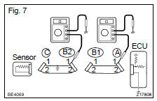
- Disconnect connector "B" and measure the resistance
between terminal 1 of connector "A" and body
ground, and terminal 1 of connector "B2" and body
ground.
Between terminal 1 of connector "A" and body ground " No continuity Between terminal 1 of connector "B2" and body ground " Continuity (short) Therefore, it is found out that there is a short circuit between terminal 1 of connector "B2" and terminal 1 of connector "C".
8. CHECK AND REPLACE ECU
First check the ECU ground circuit. If it is faulty, repair it. If it is normal, the ECU could be faulty, so replace the ECU with a normal functioning one and check that the symptoms appear.
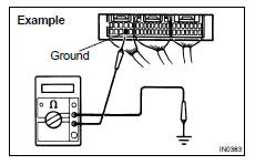
- Measure the resistance between the ECU ground terminal and the body ground.
Resistance: 1 W or less
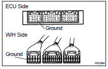
- Disconnect the ECU connector, check the ground terminals on the ECU side and the wire harness side for bend and check the contact pressure.
For all of vehicles
How to troubleshoot ecu controlled systems
How to use the diagnostic chart and inspection
How to use this manual
Identification information
Repair instructions
Repair instructions
Vehicle lift and support locations
Toyota Land Cruiser Service Manual
Categories
