 Toyota Land Cruiser Service ManualSteering » Power tilt and power telescopic steering
column
Toyota Land Cruiser Service ManualSteering » Power tilt and power telescopic steering
column
Disassembly
Disassembly
NOTICE: When using a vise, do not overtighten it.
1. REMOVE NO. 2 LOWER COVER
Remove the 2 nuts and lower side No. 2 lower cover.
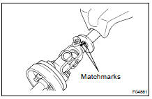
2. REMOVE INTERMEDIATE SHAFT ASSEMBLY
(a) Place matchmarks on the intermediate shaft assembly and main shaft assembly.
(b) Remove the bolt and intermediate shaft assembly with the upper side No. 2 lower cover.
(c) Remove the thrust stopper from the main shaft assembly.
3. REMOVE TRANSPONDER KEY AMPLIFIER
(a) Widen the claw humg on the upper bracket by approx. 1.0 mm (0.039 in.) using a screwdriver.
(b) Pull the transponder key amplirier toward the rear of the vehicle with the claw open.
NOTICE: Take care not to use excessive force to prevent the case from being damage.
4. REMOVE CONNECTOR BRACKET
Remove the bolt and connector bracket.
5. REMOVE STEERING COLUMN PROTECTOR NO. 1
Remove the bolt and steering column protector No. 1.
6. REMOVE TURN SIGNAL BRACKET
Remove the 3 bolts and turn signal bracket.
7. REMOVE POWER TILT MOTOR
(a) Using a hexagon wrench, remove the support stopper bolt.
(b) Remove the stopper spring and stopper No. 1.
(c) Using a hexagon wrench, remove the 2 tilt steering bolts and power tilt motor.
(d) Using a screwdriver, remove the 2 E-rings.
(e) Remove the 2 support stopper bolt bushings from the power tilt motor.
8. REMOVE ADJUSTING NUT NO. 1
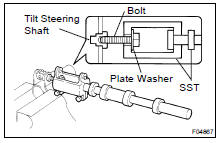
(a) Set SST, a plate washer (36 mm outer diameter) and bolt (6 mm normal diameter, 1.0 mm pitch, 50 mm length), as shown.
SST 09910-00015 (09911-0001 1, 09912-00010)
Reference:
Plate washer 90201-10201
Bolt 91111-51050
(b) Remove the 2 tilt steering shafts by using the sliding hammer on SST.
(c) Remove the adjusting nut No. 1.
(d) Remove the 2 support stopper bolt bushings from the adjusting nut No. 1.
9. REMOVE POWER TELESCOPIC MOTOR
(a) Remove the 2 bolts and power telescopic motor.
(b) Remove the telescopic steering column cable.
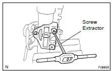
10. REMOVE COLUMN UPPER BRACKET AND COLUMN UPPER CLAMP
(a) Remove the column tube stopper.
(b) Using a centering punch, mark the center of the 2 tapered- head bolts.
(c) Using a 3 - 4 mm (0.12 - 0.16 in.) drill, drill into the 2 bolts.
(d) Using a screw extractor, remove the 2 bolts, column upper bracket and column upper clamp.
(e) Using a hexagon wrench, remove the 2 telesco lever lock bolts.
(f) Remove the 2 telescopic steering wedge lock springs, 2 steering lock wedges and column upper bracket and column upper clamp.
11. REMOVE COLUMN TUBE SUPPORT
(a) Remove the bolt.
(b) Remove the column tube support with tube attachment.
(c) Remove the tube attachment from the column tube support.
12. REMOVE 2 ENERGY ABSORBING PLATES
(a) Using pliers, remove the 2 energy absorbing clips.
(b) Remove the 2 energy absorbing plates and 2 energy absorbing guides.
13. REMOVE TELESCOPIC STEERING SLIDER SUPPORT
Remove the 2 bolts and telescopic steering slider support.
14. REMOVE TELESCOPIC STEERING BUSHING
15. REMOVE TELESCOPIC STEERING SLIDER
16. REMOVE STEERING COLUMN BRACKET SPACER
17. REMOVE TELESCOPIC STEERING SCREW
Remove the nut, 4 energy absorber cushions, 2 bearings and telescopic steering screw.
18. REMOVE COLUMN UPPER TUBE SUB-ASSEMBLY WITH MAIN SHAFT ASSEMBLY
(a) Using a screwdriver, remove the lower side snap ring from the main shaft assembly.
(b) Using a hexagon wrench, remove the 2 tilt steering bolts and column upper tube sub-assembly with the main shaft assembly.
(c) Remove the column upper tube assembly from the break away bracket.
(d) Remove the 2 support stopper bolt bushings from the column upper tube assembly.
(e) Remove the 3 bushings from the break away bracket.
19. REMOVE MAIN SHAFT ASSEMBLY
(a) Using SST, compress the compression spring.
SST 09950-4001 1 (09958-04011)
NOTICE: Do not bend the universal joint of the shaft assembly more than 20.
(b) Using a snap ring expander, remove the upper side snap ring.
(c) Remove the main shaft assembly from the column upper tube sub-assembly.
(d) Remove the compression spring and bearing thrust collar from the main shaft assembly.
INSPECTION ( SR-20 )
INSTALLATION ( SR-24 )
Disassembly
Reassembly
Toyota Land Cruiser Service Manual
Categories
