 Toyota Land Cruiser Service ManualBody Electrical
Defogger system
Defogger system
INSPECTION
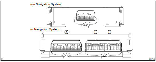
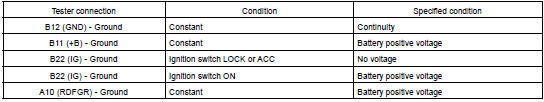
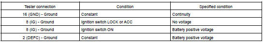
1. INSPECT DEFOGGER SWITCH CIRCUIT
Disconnect the connector from the panel switch and inspect the connector on wire harness side, as shown in the chart.
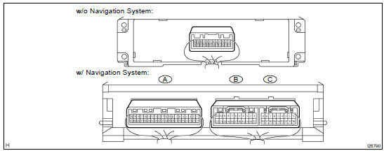
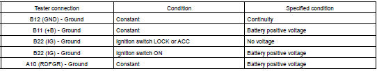
w/ Navigation:
w/o Navigation:
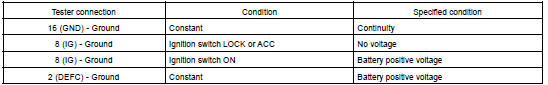
If the circuit is not as specified, replace the switch.
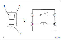
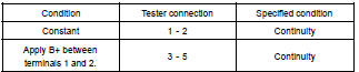
2. INSPECT DEFOGGER RELAY CONTINUITY
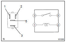
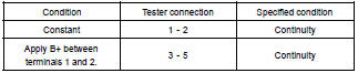
If continuity is not as specified, replace the relay.
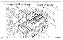
3. INSPECT ENGINE ROOM R/B RELAY CIRCUIT (See Pase BE-15 )
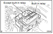
HINT: The mirror heater relay is built in engine room junction block.
Also the relay is constructed with a relay block that is in the junction block as a unit. To disconnect the wire harness connecting with relay block is impossible. If the relay has a malfunction, replace it with junction block assembly wire harness together.
4. INSPECT DEFOGGER WIRE
NOTICE:
- When cleaning the glass, use a soft, dry cloth, and wipe the glass in the direction of the wire. Take care not to damage the wires.
- Do not use detergents or glass cleaners with abrasive ingredients.
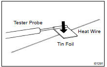
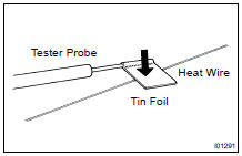
- When measuring voltage, wrap a piece of tin foil around the tip of the negative probe and press the foil against the wire with your finger, as shown.
(a) Turn the ignition switch ON.
(b) Turn the defogger switch ON.
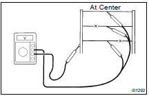
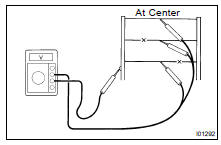
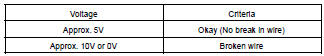
(c) Inspect the voltage at the center of each heat wire, as shown.
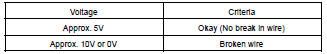
HINT: If there is approximately 10 V, the wire is broken between the center of the wire and the positive (+) end. If there is no voltage, the wire is broken between the center of the wire and ground.
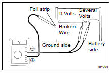
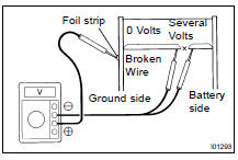
(d) Place the voltmeter positive (+) lead against the defogger wire on the battery side.
(e) Place the voltmeter negative (-) lead with the foil strip against the wire on the ground side.
(f) Slide the positive (+) lead from battery to ground side.
(g) The point where the voltmeter deflects from several V to zero V is the place where the defogger wire is broken.
HINT: If the heat wire is not broken, the voltmeter indicates 0 V at the positive (+) end of the heat wire but voltage gradually increases to about 12 V as the meter probe moves to the other end.
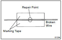
5. IF NECESSARY, REPAIR DEFOGGER WIRE
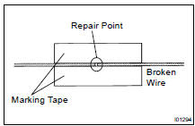
(a) Clean the broken wire tips with grease, wax and silicone remover.
(b) Place the masking tape along both sides of the wire for repair.
(c) Thoroughly mix the repair agent (Dupont paste No.
4817).
(d) Using a fine tip brush, apply a small amount of the agent to the wire.
(e) After a few minutes, remove the masking tape.
(f) Do not repair the defogger wire for at least 24 hours.
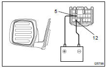
6. w/ Mirror heater: INSPECT MIRROR HEATER OPERATION
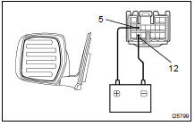
(a) Connect the positive (+) lead from the battery to terminal 5 and the negative (-) lead to terminal 12.
(b) Check that the mirror becomes warm.
HINT: It will take a short time for the mirror to become warm.
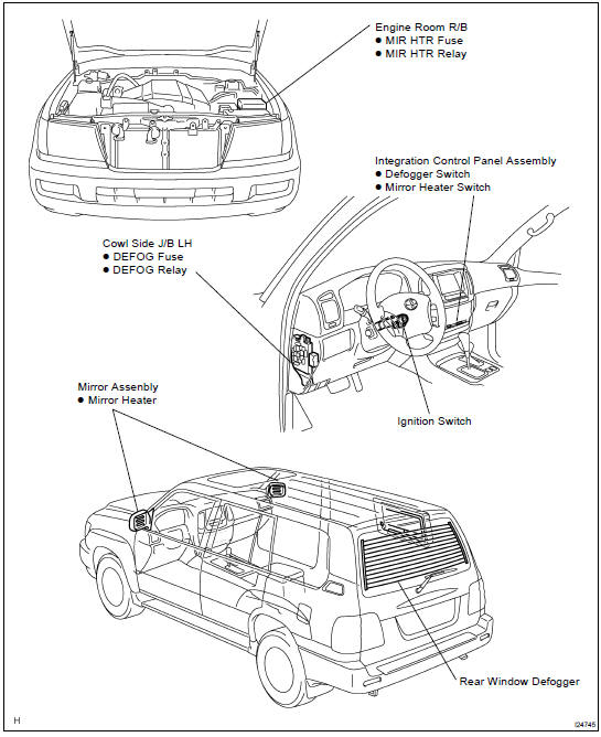
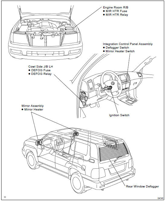
LOCATION
INSPECTION
1. INSPECT DEFOGGER SWITCH CIRCUIT
Disconnect the connector from the panel switch and inspect the connector on wire harness side, as shown in the chart.
w/ Navigation:
w/o Navigation:
If the circuit is not as specified, replace the switch.
2. INSPECT DEFOGGER RELAY CONTINUITY
If continuity is not as specified, replace the relay.
3. INSPECT ENGINE ROOM R/B RELAY CIRCUIT (See Pase BE-15 )
HINT: The mirror heater relay is built in engine room junction block.
Also the relay is constructed with a relay block that is in the junction block as a unit. To disconnect the wire harness connecting with relay block is impossible. If the relay has a malfunction, replace it with junction block assembly wire harness together.
4. INSPECT DEFOGGER WIRE
NOTICE:
- When cleaning the glass, use a soft, dry cloth, and wipe the glass in the direction of the wire. Take care not to damage the wires.
- Do not use detergents or glass cleaners with abrasive ingredients.
- When measuring voltage, wrap a piece of tin foil around the tip of the negative probe and press the foil against the wire with your finger, as shown.
(a) Turn the ignition switch ON.
(b) Turn the defogger switch ON.
(c) Inspect the voltage at the center of each heat wire, as shown.
HINT: If there is approximately 10 V, the wire is broken between the center of the wire and the positive (+) end. If there is no voltage, the wire is broken between the center of the wire and ground.
(d) Place the voltmeter positive (+) lead against the defogger wire on the battery side.
(e) Place the voltmeter negative (-) lead with the foil strip against the wire on the ground side.
(f) Slide the positive (+) lead from battery to ground side.
(g) The point where the voltmeter deflects from several V to zero V is the place where the defogger wire is broken.
HINT: If the heat wire is not broken, the voltmeter indicates 0 V at the positive (+) end of the heat wire but voltage gradually increases to about 12 V as the meter probe moves to the other end.
5. IF NECESSARY, REPAIR DEFOGGER WIRE
(a) Clean the broken wire tips with grease, wax and silicone remover.
(b) Place the masking tape along both sides of the wire for repair.
(c) Thoroughly mix the repair agent (Dupont paste No.
4817).
(d) Using a fine tip brush, apply a small amount of the agent to the wire.
(e) After a few minutes, remove the masking tape.
(f) Do not repair the defogger wire for at least 24 hours.
6. w/ Mirror heater: INSPECT MIRROR HEATER OPERATION
(a) Connect the positive (+) lead from the battery to terminal 5 and the negative (-) lead to terminal 12.
(b) Check that the mirror becomes warm.
HINT: It will take a short time for the mirror to become warm.
LOCATION
Antenna
Audio system
Body electrical system
Combination meter
Combination meter
Compass
Defogger system
Engine immobiliser system
Fog light system
Garage door opener system
Headlight and taillight system
Horn system
Interior light system
Ignition switch and key unlock warning switch
Multi display
Overhead junction block
Power door lock control system
Power window control system
Stop light system
Sliding roof system
Troubleshooting
Turn signal and hazard warning system
Wiper and washer system
Wireless door lock control system
Toyota Land Cruiser Service Manual
Categories
